
Servo-Tester-NE555

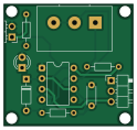
About the Servo-Tester-NE555 PCB
Servo-Tester-NE555 is an open source PCB design by ramuroy, published on GitHub under the MIT license. It is a 2-layer board measuring 30.9 × 29.2 mm, with 10 components from 10 distinct parts.
Other key parts include the NE555P. By type, the board carries 3 resistors, 2 connectors, 2 diodes, 1 IC and 1 capacitor.
It belongs with the robotics & motion designs in this gallery.
From the project
🔧 A basic servo motor tester using the NE555 timer in astable mode. 🧠 Designed in KiCad with adjustable PWM output ⚙️ for controlling servo motors.
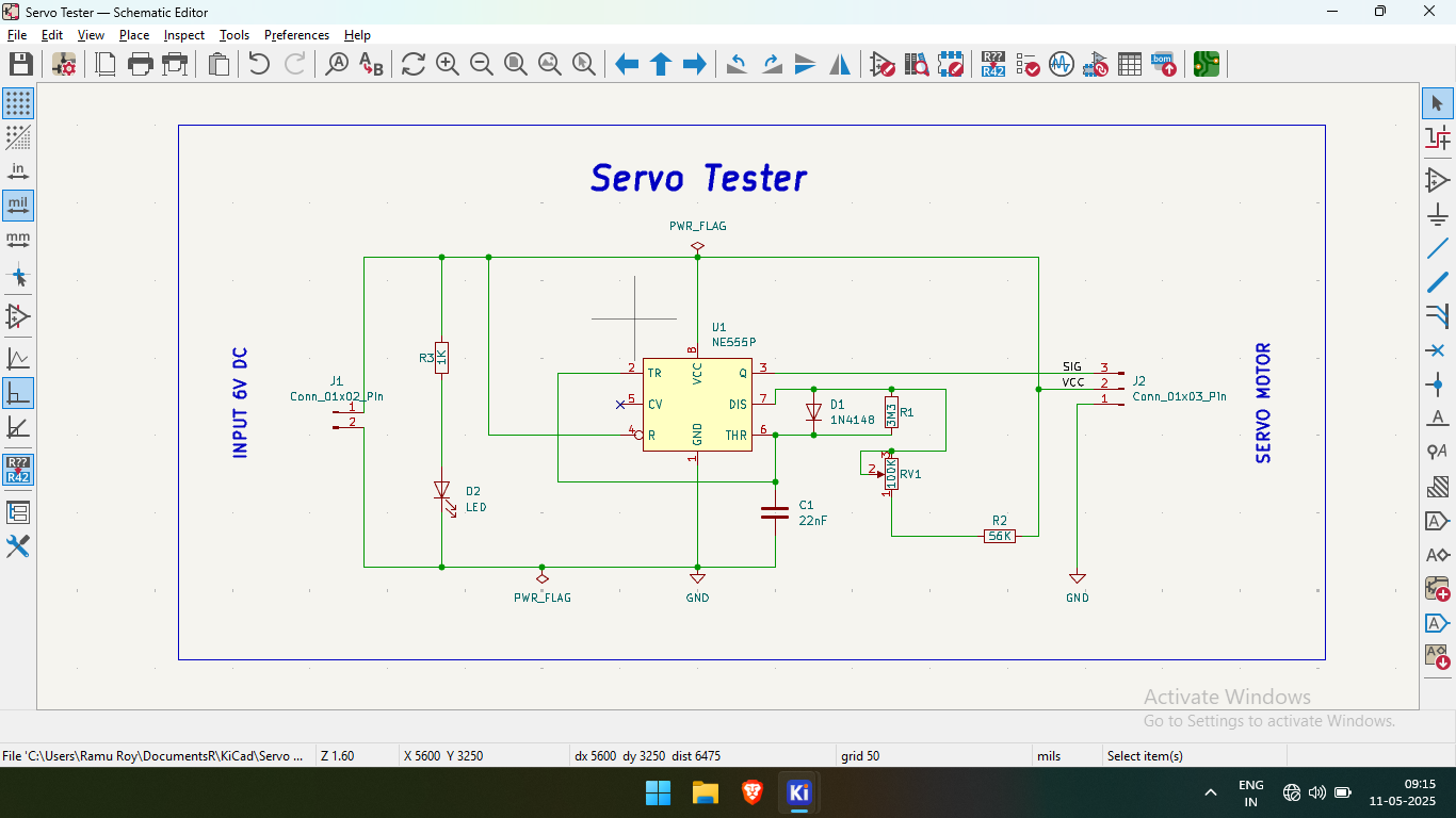
Main components on the Servo-Tester-NE555
Servo-Tester-NE555 bill of materials (BOM)
10 components, 10 distinct parts.
| Qty | Part | Footprint | Refs |
|---|---|---|---|
| 1 | NE555P | DIP-8_W7.62mm | U1 |
| 1 | Conn_01x02_Pin | PinHeader_1x02_P2.54mm_Horizontal | J1 |
| 1 | Conn_01x03_Pin | PinHeader_1x03_P2.54mm_Horizontal | J2 |
| 1 | 100K | Potentiometer_Alps_RK163_Single_Horizontal | RV1 |
| 1 | 1N4148 | D_DO-35_SOD27_P7.62mm_Horizontal | D1 |
| 1 | LED | LED_D3.0mm | D2 |
| 1 | 22nF | C_Disc_D4.3mm_W1.9mm_P5.00mm | C1 |
| 1 | 3M3 | R_Axial_DIN0204_L3.6mm_D1.6mm_P7.62mm_Horizontal | R1 |
| 1 | 56K | R_Axial_DIN0204_L3.6mm_D1.6mm_P7.62mm_Horizontal | R2 |
| 1 | 1K | R_Axial_DIN0204_L3.6mm_D1.6mm_P7.62mm_Horizontal | R3 |
Servo-Tester-NE555 design files
The KiCad project lives in the ramuroy/Servo-Tester-NE555 repository on GitHub; these links point at the commit this page was built from.
Servo-Tester-NE555: common questions
How big is the Servo-Tester-NE555 PCB?
The Servo-Tester-NE555 measures 30.9 × 29.2 mm, has 2 copper layers and is 1.6 mm thick.
How many components are on the Servo-Tester-NE555?
10 components, from 10 distinct parts. The full bill of materials is listed on this page.
Where can I download the Servo-Tester-NE555 design files?
From the ramuroy/Servo-Tester-NE555 repository on GitHub, which has the KiCad layout; the links under Design files point to each one.
Can I use the Servo-Tester-NE555 design in my own project?
Yes, under the terms of its MIT license, which ramuroy chose for the repository.
Similar boards

Stack chan
stack-chan
50 × 50 mm33 parts2LApache-2.01.7k
Cube batteryboard
willem-pennings
95 × 95 mm4 parts2LGPL-3.01.1k
11ua
rene-dev
57.3 × 19 mm26 parts2LGPL-3.0979
Trollerv2
100 × 75 mm33 parts4LGPL-3.0979
Powerstep
95.2 × 71.5 mm28 parts4LGPL-3.0979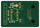
Diff driver
32 × 22 mm14 parts2LGPL-3.0979