
Diy shift indicator

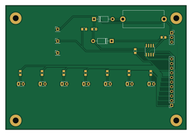
About the Diy shift indicator PCB
Diy shift indicator is an open source AVR/Arduino PCB design by Rav4s, published on GitHub under the GPL-3.0 license. It is a 2-layer board measuring 99 × 68 mm, with 27 components from 20 distinct parts.
Its main chip is the PPTC111LFBN-RC, from the AVR/Arduino family. By type, the board carries 9 diodes, 9 resistors, 5 connectors, 2 capacitors and 1 fuse.
It belongs with the displays & leds designs in this gallery.
From the project
A K-Line shift indicator for manual transmission cars like my Mazda MX-5
Diy shift indicator bill of materials (BOM)
27 components, 20 distinct parts — part numbers from the project's BOM.
| Qty | Part | Footprint | Refs |
|---|---|---|---|
| 1 | PPTC111LFBN-RC Arduino Connector | PinSocket_1x11_P2.54mm_Vertical | J1 |
| 1 | PH1-01-UA GND | PinHeader_1x01_P2.54mm_Vertical | J2 |
| 1 | PH1-01-UA Batt | PinHeader_1x01_P2.54mm_Vertical | J3 |
| 1 | PH1-01-UA LIN | PinHeader_1x01_P2.54mm_Vertical | J4 |
| 1 | PPPC031LFBN-RC OBDII Connector | PinSocket_1x03_P2.54mm_Vertical | J13 |
| 1 | F6094-ND & 0235.200HXP Fuse (200mA) | Fuseholder_Cylinder-5x20mm_Stelvio-Kontek_PTF78_Horizontal_Open | F1 |
| 1 | SN65HVDA195QDRQ1 ~ | SOIC-8_3.9x4.9mm_P1.27mm | SN65HVDA195 |
| 2 | 1N4007-T 1N4007 | D_DO-41_SOD81_P10.16mm_Horizontal | D1, D2 |
| 1 | LTL-709L Green LED 1 | LED_D1.8mm_W3.3mm_H2.4mm | D3 |
| 1 | LTL-709L Green LED 2 | LED_D1.8mm_W3.3mm_H2.4mm | D4 |
| 1 | LTL-709L Green LED 3 | LED_D1.8mm_W3.3mm_H2.4mm | D5 |
| 1 | LTL-709Y Yellow LED 1 | LED_D1.8mm_W3.3mm_H2.4mm | D6 |
| 1 | LTL-709Y Yellow LED 2 | LED_D1.8mm_W3.3mm_H2.4mm | D7 |
| 1 | LTL-709E Red LED 1 | LED_D1.8mm_W3.3mm_H2.4mm | D8 |
| 1 | LTL-709E Red LED 2 | LED_D1.8mm_W3.3mm_H2.4mm | D9 |
| 1 | 0805B104K101CC 100nF | C_0805_2012Metric_Pad1.18x1.45mm_HandSolder | C1 |
| 1 | 0805B221K500BD 220pF | C_0805_2012Metric_Pad1.18x1.45mm_HandSolder | C2 |
| 1 | RC0805FR-071KL 1kΩ | R_0805_2012Metric_Pad1.20x1.40mm_HandSolder | R1 |
| 1 | ERJ-6ENF4991V 4.6kΩ | R_0805_2012Metric_Pad1.20x1.40mm_HandSolder | R2 |
| 7 | CRGCQ0805F220R 220Ω | R_0805_2012Metric_Pad1.20x1.40mm_HandSolder | R3, R4, R5, R6, R7, R8, R9 |
Diy shift indicator design files
The KiCad project lives in the Rav4s/diy-shift-indicator repository on GitHub; these links point at the commit this page was built from.
Diy shift indicator: common questions
What microcontroller does the Diy shift indicator use?
The Diy shift indicator is built around the PPTC111LFBN-RC, from the AVR/Arduino family.
How big is the Diy shift indicator PCB?
The Diy shift indicator measures 99 × 68 mm, has 2 copper layers and is 1.6 mm thick.
How many components are on the Diy shift indicator?
27 components, from 20 distinct parts, with part numbers taken from the project's own BOM. The full bill of materials is listed on this page.
Where can I download the Diy shift indicator design files?
From the Rav4s/diy-shift-indicator repository on GitHub, which has the KiCad layout, the schematic and the BOM; the links under Design files point to each one.
Can I use the Diy shift indicator design in my own project?
Yes, under the terms of its GPL-3.0 license, which Rav4s chose for the repository.
Can I test firmware for the Diy shift indicator without the hardware?
Yes. HardLabs builds a simulation of the board from its netlist and BOM, so you can run and debug AVR/Arduino firmware against it before you order a PCB.
Similar boards
 AVR/Arduino
ModuleV450
stuartpittaway
30 × 61.4 mm39 parts2LCC-BY-NC-4.01.1k AVR/Arduino
V4
30 × 50 mm38 parts2LCC-BY-NC-4.01.1k AVR/Arduino
Easyduino Atmega
Hanqaqa
68.8 × 53.6 mm35 parts4LCERN-OHL-P-2.0746 AVR/Arduino
Easyduino Atmega Nano
43.4 × 18 mm30 parts4LCERN-OHL-P-2.0746 AVR/Arduino
UsbGpib
xyphro
54 × 15 mm21 parts2LMIT683 AVR/Arduino
Lumberjack
peej
284.7 × 94.2 mm149 parts2LMIT402