
ROM

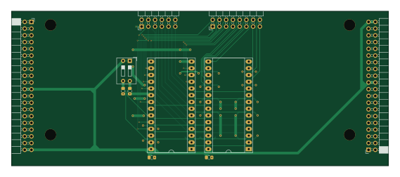
About the ROM PCB
ROM is an open source PCB design by rraider, published on GitHub under the MIT license. It is a 2-layer board measuring 142 × 58.3 mm, with 11 components from 7 distinct parts.
Other key parts include the 28c64. By type, the board carries 4 connectors, 2 ICs, 2 capacitors, 2 resistors and 1 switch.
From the project
Entwicklung eines turingvollständigen, primitiven Microcontroller in der Software Digital
Entwicklung eines turingvollständigen, primitiven Microcontroller in der Software Digital
Sponsored by JLCPCB https://jlcpcb.com/RAT
Main components on the ROM
ROM bill of materials (BOM)
11 components, 7 distinct parts.
| Qty | Part | Footprint | Refs |
|---|---|---|---|
| 2 | 28c64 | DIP-28_W15.24mm_Socket_LongPads | U30, U31 |
| 2 | Conn_02x20_Counter_Clockwise | PinSocket_2x20_P2.54mm_Horizontal | J1, J2 |
| 1 | Conn_02x08_Counter_Clockwise | PinHeader_2x08_P2.54mm_Horizontal | J4 |
| 1 | Conn_02x06_Counter_Clockwise | PinHeader_2x06_P2.54mm_Horizontal | J6 |
| 1 | SW_DIP_x02 | SW_DIP_SPSTx02_Slide_9.78x7.26mm_W7.62mm_P2.54mm | SW3 |
| 2 | C | C_0805_2012Metric_Pad1.15x1.40mm_HandSolder | C50, C51 |
| 2 | R | R_0805_2012Metric_Pad1.15x1.40mm_HandSolder | R269, R270 |
ROM design files
The KiCad project lives in the rraider/Seminarkurs2021 repository on GitHub; these links point at the commit this page was built from.
ROM: common questions
How big is the ROM PCB?
The ROM measures 142 × 58.3 mm, has 2 copper layers and is 1.6 mm thick.
How many components are on the ROM?
11 components, from 7 distinct parts. The full bill of materials is listed on this page.
Where can I download the ROM design files?
From the rraider/Seminarkurs2021 repository on GitHub, which has the KiCad layout and the schematic; the links under Design files point to each one.
Can I use the ROM design in my own project?
Yes, under the terms of its MIT license, which rraider chose for the repository.
More boards in Seminarkurs2021
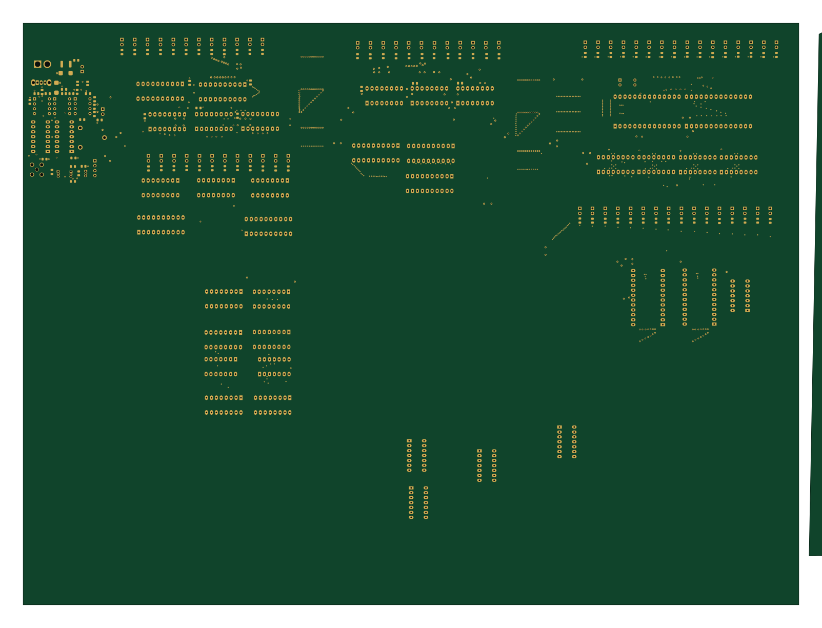
SPU2
400 × 300 mm736 parts2LMIT7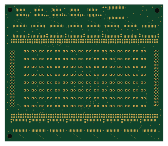
GFX
142 × 122 mm302 parts4LMIT7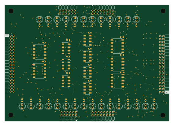
MARMEM
142 × 100.2 mm86 parts2LMIT7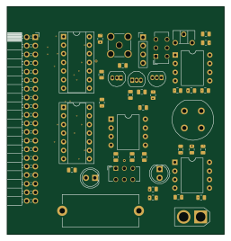
CLK stdln
64 × 67 mm43 parts2LMIT7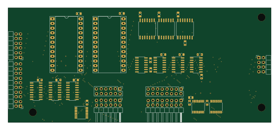
RAM
142 × 62 mm41 parts4LMIT7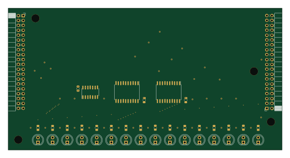
IR
142 × 73.7 mm40 parts2LMIT7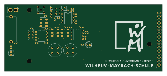
CLK
142 × 60 mm39 parts2LMIT7
ADDR
469.5 × 64.3 mm38 parts2LMIT7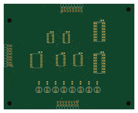
ALU
119 × 96 mm31 parts2LMIT7
DATA
469.5 × 64.3 mm27 parts2LMIT7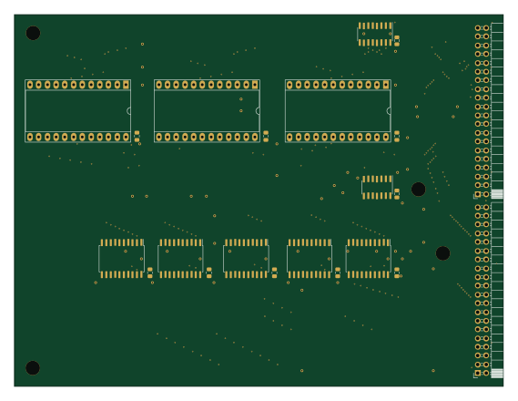
MIM
142.1 × 108 mm22 parts2LMIT7