
ECU adapter

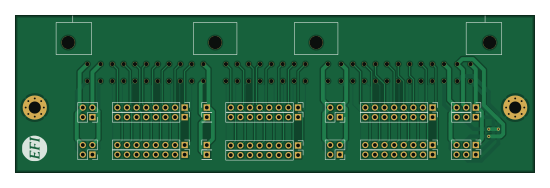
About the ECU adapter PCB
ECU adapter is an open source PCB design by rusefi, published on GitHub under the GPL-3.0 license. It is a 2-layer board measuring 137.2 × 41.5 mm, with 25 components from 5 distinct parts.
From the project
rusefi - GPL internal combustion engine control unit
ECU adapter bill of materials (BOM)
25 components, 5 distinct parts — part numbers from the project's BOM.
| Qty | Part | Footprint | Refs |
|---|---|---|---|
| 4 | CONN_3 | PinHeader_1x03_P2.54mm_Vertical | P1, P2, P13, P14 |
| 4 | Conn_01x04_Male | PinHeader_2x02_P2.54mm_Vertical | P3, P4, P42, P43 |
| 4 | CONN_1 | PinHeader_1x01_P2.54mm_Vertical | P7, P8, P19, P20 |
| 1 | 0176122-06 | 176122-6 | P25 |
| 12 | CONN_8 | PinHeader_1x08_P2.54mm_Vertical | P26, P27, P28, P29, P30, P31, P32, P33 +4 |
ECU adapter design files
The KiCad project lives in the rusefi/rusefi repository on GitHub; these links point at the commit this page was built from.
ECU adapter: common questions
How big is the ECU adapter PCB?
The ECU adapter measures 137.2 × 41.5 mm, has 2 copper layers and is 1.6002 mm thick.
How many components are on the ECU adapter?
25 components, from 5 distinct parts, with part numbers taken from the project's own BOM. The full bill of materials is listed on this page.
Where can I download the ECU adapter design files?
From the rusefi/rusefi repository on GitHub, which has the KiCad layout and the BOM; the links under Design files point to each one.
Can I use the ECU adapter design in my own project?
Yes, under the terms of its GPL-3.0 license, which rusefi chose for the repository.
More boards in rusefi
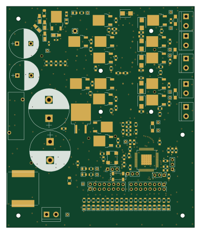
Common Rail MC33816 board
101.6 × 119.6 mm183 parts2LGPL-3.01.2k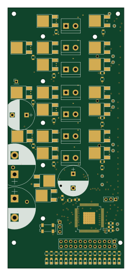
Common Rail PT2000 board
61 × 136.5 mm168 parts2LGPL-3.01.2k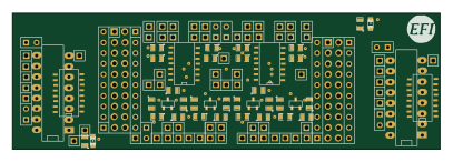
Stimulator
101.6 × 32.4 mm150 parts2LGPL-3.01.2k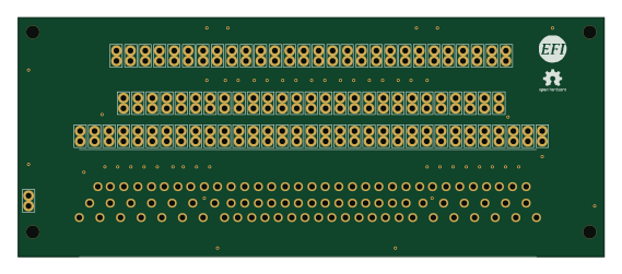
88 Pin Vag Breakout
142 × 58 mm91 parts2LGPL-3.01.2k STM32
STM32176 pin board
61.8 × 73.2 mm76 parts2LGPL-3.01.2k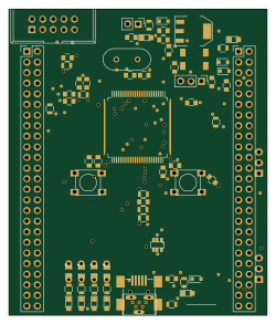 STM32
STM32Brain board STM32F407
61.8 × 73.2 mm69 parts2LGPL-3.01.2k
Breakout 112pin Connector
174 × 58 mm39 parts2LGPL-3.01.2k
134pin 7-967288-1
139.7 × 73.7 mm38 parts2LGPL-3.01.2k
VR board
38.1 × 12.7 mm37 parts2LGPL-3.01.2k
Breakout 60pin EEC-IV
139.7 × 62.2 mm15 parts2LGPL-3.01.2k
Eecv breakout
140.8 × 53.7 mm9 parts4LGPL-3.01.2k