
ESR-System

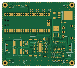
About the ESR-System PCB
ESR-System is an open source RP2040/RP2350 PCB design by sandeepzgk, published on GitHub under the MIT license. It is a 2-layer board measuring 80 × 70 mm, with 86 components from 32 distinct parts.
Its main chip is the Pico, from the RP2040/RP2350 family. Other key parts include the LM7812S-TR, PCM5100APWR, LM78M05CDTX/NOPB, AP7333-33SRG-7 and TPA3112D1PWPR. By type, the board carries 42 capacitors, 21 resistors, 6 ICs, 6 inductors, 5 diodes and 3 connectors.
It belongs with the audio designs in this gallery.
From the project
Notable parts - DAC: PCM5100A - Amplifier: TPA3112D1 - Regulators: LM78M05C, LM7812S, LM1085IS-12, AP7333-33 - Inductors/caps/resistors; Pico headers/footprints; custom logos
Notable parts - DAC: PCM5100A - Amplifier: TPA3112D1 - Regulators: LM78M05C, LM7812S, LM1085IS-12, AP7333-33 - Inductors/caps/resistors; Pico headers/footprints; custom logos
Generate fabrication - Use KiCad’s Plot and Fabrication Toolkit (options in fabrication-toolkit-options.json) - Export Gerbers, drill files, position files, and BOM as needed
JLC integration workflow - jlcimporter.py wraps JLC2KiCadLib to create per‑part libraries under PCB/lib// - It normalizes filenames (symbol.kicadsym, footprint.kicadmod, model.step) and updates lib tables - Run from PCB/: python jlcimporter.py…
Main components on the ESR-System
ESR-System bill of materials (BOM)
86 components, 32 distinct parts — part numbers from the project's BOM.
| Qty | Part | Footprint | Refs |
|---|---|---|---|
| 1 | DNP Pico | RPi_Pico_SMD_TH | U1 |
| 1 | LM7812S-TR | footprint | U2 |
| 1 | PCM5100APWR | TSSOP-20_4.4x6.5mm_P0.65mm | U3 |
| 1 | LM78M05CDTX/NOPB | footprint | U8 |
| 1 | AP7333-33SRG-7 | footprint | U9 |
| 1 | TPA3112D1PWPR | footprint | U11 |
| 2 | KF301-5_0-2P | footprint | J1, J2 |
| 1 | Conn_01x02_Pin | PinHeader_1x02_P2.54mm_Vertical | J3 |
| 1 | C719176 10K | footprint | RV1 |
| 1 | PTS636SK25SMTRLFS | footprint | SW1 |
| 1 | SS-12D11L7 | SS-12D11L7 | SW2 |
| 5 | C89811 LED_Small | LED_0603_1608Metric | D1, D2, D3, D4, D5 |
| 2 | 80Ω | L_0805_2012Metric | FB1, FB3 |
| 2 | 75Ω | L_1806_4516Metric | FB2, FB4 |
| 2 | 22UH 22uH | footprint | L1, L2 |
| 2 | 2.2NF 2.2uF | C_0603_1608Metric | C1, C4 |
| 2 | 2.2NF 2.2nF | C_0603_1608Metric | C2, C3 |
| 11 | 100NF 100nF | C_0603_1608Metric | C5, C8, C9, C11, C14, C15, C16, C17 +3 |
| 9 | 1UF 1uF | C_0603_1608Metric | C6, C13, C20, C21, C29, C30, C31, C32 +1 |
| 4 | 10UF 10uF | C_0603_1608Metric | C7, C10, C12, C22 |
Show 12 more
| Qty | Part | Footprint | Refs |
|---|---|---|---|
| 1 | 0.22UF 0.22uF | C_0603_1608Metric | C18 |
| 4 | 1NF 1nF | C_0603_1608Metric | C23, C26, C34, C36 |
| 2 | 100UF 100uF | CP_Elec_6.3x5.4 | C25, C28 |
| 2 | 0.68UF 0.68uF | C_0603_1608Metric | C35, C37 |
| 2 | 0.47UF 0.47uF | C_0603_1608Metric | C38, C39 |
| 2 | 1UF 1nF | C_0603_1608Metric | C40, C41 |
| 1 | 68UF 68uF | footprint | C43 |
| 3 | 56R | R_0603_1608Metric | R1, R2, R3 |
| 8 | 10K | R_0603_1608Metric | R4, R7, R15, R16, R17, R18, R19, R20 |
| 2 | 470R | R_0603_1608Metric | R5, R6 |
| 5 | 1K | R_0603_1608Metric | R11, R12, R13, R14, R21 |
| 3 | 10R | R_0603_1608Metric | R22, R23, R24 |
ESR-System design files
The KiCad project lives in the sandeepzgk/ESR-System repository on GitHub; these links point at the commit this page was built from.
- LayoutPCB/sr-device.kicad_pcb
- SchematicPCB/sr-device.kicad_sch
- BOMPCB/production/v1/BOM.csv
ESR-System: common questions
What microcontroller does the ESR-System use?
The ESR-System is built around the Pico, from the RP2040/RP2350 family.
How big is the ESR-System PCB?
The ESR-System measures 80 × 70 mm, has 2 copper layers and is 1.6 mm thick.
How many components are on the ESR-System?
86 components, from 32 distinct parts, with part numbers taken from the project's own BOM. The full bill of materials is listed on this page.
Where can I download the ESR-System design files?
From the sandeepzgk/ESR-System repository on GitHub, which has the KiCad layout, the schematic and the BOM; the links under Design files point to each one.
Can I use the ESR-System design in my own project?
Yes, under the terms of its MIT license, which sandeepzgk chose for the repository.
Can I test firmware for the ESR-System without the hardware?
Yes. HardLabs builds a simulation of the board from its netlist and BOM, so you can run and debug RP2040/RP2350 firmware against it before you order a PCB.
Similar boards
 RP2040/RP2350
Open Book Abridged Edition
joeycastillo
85 × 115 mm29 parts2LCC-BY-SA-4.08.1k RP2040/RP2350
Corne
foostan
277.2 × 107.5 mm164 parts2LCC-BY-4.07.7k RP2040/RP2350
Corne
277.2 × 107.5 mm164 parts2LCC-BY-4.07.7k RP2040/RP2350
LogicAnalyzer
gusmanb
57 × 55.2 mm6 parts2LGPL-3.05.0k RP2040/RP2350
Jitx design
55.5 × 65 mm26 parts4LGPL-3.05.0k RP2040/RP2350
Main
google
98 × 71 mm102 parts2LApache-2.02.9k