
Ui board

About the Ui board
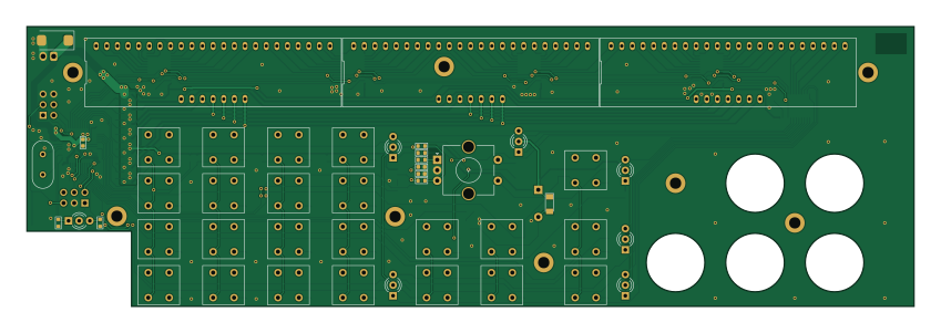
Ui board is an open source STM32 PCB design by sbstnh, published on GitHub under the BSD-3-Clause license. It is a 2-layer board measuring 212 × 67 mm, with 124 components from 56 distinct parts.
Its main chip is the STM32L010C6, from the STM32 family. Other key parts include the DYSR00P401101, STP16CP05 and 74HC14. By type, the board carries 32 diodes, 27 resistors, 24 switches, 18 capacitors, 10 ICs and 8 transistors.
From the project
A SCPI programmable precision resistor
WARNING: The programmable power resistor presented is mains powered. On the power supply board there will be mains/line voltage. Working with/on such devices can lead to damage, injury or death. Don't do it if you're not qualified or authorized to do so. You use the circuits described at you own risk. You have to make sure that the circuit is safe and adheres to the applicable standards in your location. You might operate the mainboard and ui board more safely with a bench or external power supply.

Main components on the Ui board
Ui board bill of materials (BOM)
124 components, 56 distinct parts.
| Qty | Part | Footprint | Refs |
|---|---|---|---|
| 1 | STM32L010C6 | LQFP-48_7x7mm_P0.5mm | U1 |
| 3 | DYSR00P401101 | DYSR00P401101 | U2, U5, U9 |
| 5 | STP16CP05 | TSSOP-24_4.4x7.8mm_P0.65mm | U3, U4, U6, U8, U10 |
| 1 | 74HC14 | SO-14_3.9x8.65mm_P1.27mm | U7 |
| 1 | BSS138 | SOT-23 | Q1 |
| 7 | IRLML6402 | SOT-23 | Q2, Q3, Q4, Q5, Q6, Q7, Q8 |
| 1 | 16MHz | Crystal_HC49-4H_Vertical | Y1 |
| 1 | PWR3.3V | Molex_KK-254_AE-6410-02A_1x02_P2.54mm_Vertical | J1 |
| 1 | UI | PinHeader_2x03_P2.54mm_Vertical | J2 |
| 1 | Conn_02x03_Odd_Even | PinHeader_2x03_P2.54mm_Vertical | J3 |
| 1 | Buzzer | Buzzer_Ekulit_AL-60P06_D12mm_H9mm | BZ1 |
| 1 | SW_CHAN | PVA1 | SW1 |
| 1 | SW_MODE | PVA1 | SW2 |
| 1 | SW_MENU | PVA1 | SW3 |
| 1 | SW_SHIFT | PVA1 | SW4 |
| 1 | OMRB3FS | OMR_B3FS | SW5 |
| 1 | SW_7 | PVA1 | SW6 |
| 1 | SW_4 | PVA1 | SW7 |
| 1 | SW_1 | PVA1 | SW8 |
| 1 | SW_0 | PVA1 | SW9 |
Show 36 more
| Qty | Part | Footprint | Refs |
|---|---|---|---|
| 1 | SW_8 | PVA1 | SW10 |
| 1 | SW_5 | PVA1 | SW11 |
| 1 | SW_2 | PVA1 | SW12 |
| 2 | SW_DP | PVA1 | SW13, SW17 |
| 1 | SW_9 | PVA1 | SW14 |
| 1 | SW_6 | PVA1 | SW15 |
| 1 | SW_3 | PVA1 | SW16 |
| 1 | SW_LEFT | PVA1 | SW18 |
| 1 | SW_RIGHT | PVA1 | SW19 |
| 1 | SW_ENTER | PVA1 | SW20 |
| 1 | SW_BACK_DISP | PVA1 | SW21 |
| 1 | SW_INPUT | PVA1 | SW22 |
| 1 | SW_RUN_STOP | PVA1 | SW23 |
| 1 | SW_SINGLE | PVA1 | SW24 |
| 1 | 1N4148 | D_MiniMELF | D1 |
| 24 | LL4148 | D_MiniMELF | D2, D3, D4, D5, D6, D7, D8, D9 +16 |
| 1 | PWR | LED_D3.0mm-3 | D10 |
| 1 | LED_REMOTE | LED_D3.0mm-3 | D15 |
| 1 | LED_RUN_ST | LED_D3.0mm-3 | D16 |
| 1 | dnp | LED_D3.0mm-3 | D21 |
| 1 | LED_SINGLE | LED_D3.0mm-3 | D22 |
| 1 | LED_ENTRY | LED_D3.0mm-3 | D23 |
| 1 | LED_INPUT | LED_D3.0mm-3 | D24 |
| 2 | 27p | C_0603_1608Metric_Box | C1, C3 |
| 1 | 100u | CP_EIA-7343-31_Kemet-D_Pad2.25x2.55mm_HandSolder | C2 |
| 1 | 4.7u | C_0603_1608Metric_Box | C4 |
| 5 | 100n | C_0603_1608Metric_Box | C5, C6, C7, C8, C18 |
| 1 | 10n | C_0603_1608Metric_Box | C9 |
| 6 | 1u | C_0603_1608Metric_Box | C10, C11, C12, C15, C16, C17 |
| 2 | 1n | C_0603_1608Metric_Box | C13, C14 |
| 1 | 1k | R_0805_2012Metric_Box | R1 |
| 7 | dnp | R_0603_1608Metric_Box | R2, R4, R6, R7, R8, R10, R12 |
| 5 | 10k | R_0603_1608Metric_Box | R3, R16, R18, R19, R20 |
| 2 | tbd | R_0603_1608Metric_Box | R5, R9 |
| 7 | 15k | R_0603_1608Metric_Box | R11, R14, R15, R21, R23, R24, R26 |
| 5 | 1k | R_0603_1608Metric_Box | R13, R17, R22, R25, R27 |
Ui board design files
The KiCad project lives in the sbstnh/programmable_precision_resistor repository on GitHub; these links point at the commit this page was built from.
Ui board: common questions
What microcontroller does the Ui board use?
The Ui board is built around the STM32L010C6, from the STM32 family.
How big is the Ui board?
The Ui board measures 212 × 67 mm, has 2 copper layers and is 1.6 mm thick.
How many components are on the Ui board?
124 components, from 56 distinct parts. The full bill of materials is listed on this page.
Where can I download the Ui board design files?
From the sbstnh/programmable_precision_resistor repository on GitHub, which has the KiCad layout and the schematic; the links under Design files point to each one.
Can I use the Ui board design in my own project?
Yes, under the terms of its BSD-3-Clause license, which sbstnh chose for the repository.
Can I test firmware for the Ui board without the hardware?
Yes. HardLabs builds a simulation of the board from its netlist and BOM, so you can run and debug STM32 firmware against it before you order a PCB.
More boards in programmable_precision_resistor
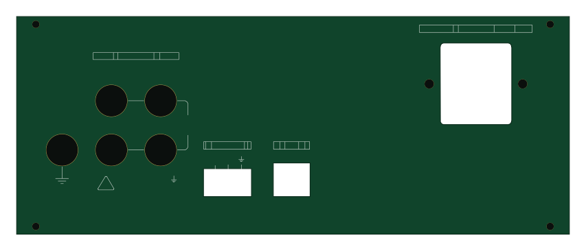
Similar boards
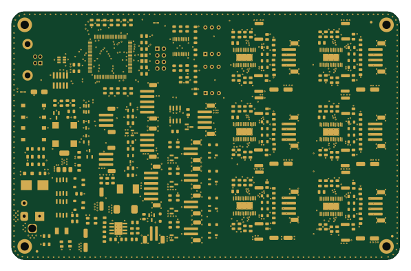 STM32
LumenPnP Motherboard
opulo-inc
149 × 95 mm296 parts4LCC-BY-SA-4.03.7k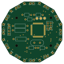 STM32
Base
google
52.3 × 52.3 mm36 parts2LApache-2.02.9k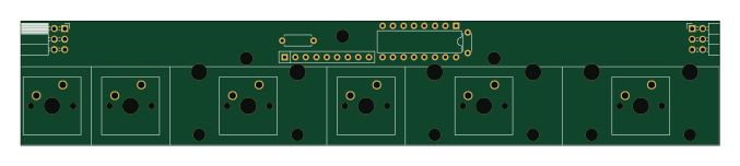 STM32
Type g
169 × 30 mm24 parts2LApache-2.02.9k STM32
Main panel
234 × 84 mm26 parts4LApache-2.02.9k STM32
Type a
150 × 30 mm14 parts2LApache-2.02.9k STM32
Type c
188 × 30 mm17 parts2LApache-2.02.9k