
Analog Redial v6

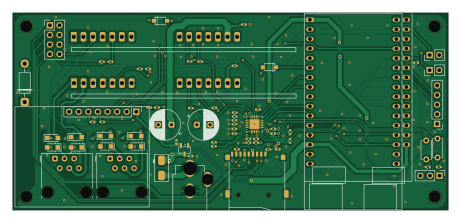
About the Analog Redial v6 PCB
Analog Redial v6 is an open source PCB design by sdylewski, published on GitHub under the MIT license. It is a 2-layer board measuring 115 × 52 mm, with 54 components from 17 distinct parts.
Other key parts include the ES8388 and XC6206P362MR. By type, the board carries 22 capacitors, 17 resistors, 11 diodes, 2 ICs and 1 connector.
It belongs with the iot & wireless designs in this gallery, and the repository also holds 4 earlier revisions of it.
From the project
A circuit board for old telephones to come back to life. Plug one or two phones in, and you can call the other phone, use bluetooth, connect to others via voip, and do a variety of other things with a plain old rotary or touch-tone phone. There's a nice web interface also!
Released, not tested yet. It should work, but no v6 board has been built. v5 (../Analog Redial v5/) is the board that has been tested; v5.1 (../Analog Redial v5.1/) is v5 with the same clone-pin fix, also not built yet.
- The clone-module footprint is corrected. On v5 the 30-pin clone's bottom-right 5V pin is wired to GND; v6 fixes that, so there is no pin to remove. - D1, the diode that joins the DC jack to the +5 V rail, is an SS34 (3 A, JLCPCB C8678) instead of v5's SS14 (1 A). Two phone lines in use, with Wi-Fi and Bluetooth, can draw 1 A or more, which is beyond the SS14's rating. Same…
Main components on the Analog Redial v6
Analog Redial v6 bill of materials (BOM)
54 components, 17 distinct parts — part numbers from the project's BOM.
| Qty | Part | Footprint | Refs |
|---|---|---|---|
| 1 | ES8388 | QFN-28-1EP_4x4mm_P0.45mm_EP2.6x2.6mm | U2 |
| 1 | XC6206P362MR | SOT-23-3 | U5 |
| 1 | PINHD_1X5_MALE PINHD_1x5_Male | PinHeader_1x05_P2.54mm_Vertical | J6 |
| 1 | TF-01A Korean Hroparts Elec | TF-01A | Card1 |
| 1 | SS34 | D_SMA | D1 |
| 2 | 1N4148 ST(Semtech) | 1N4148W_C81598 | D2, D3 |
| 8 | SM4007PL | Nexperia_CFP3_SOD-123W | D4, D5, D6, D7, D8, D9, D10, D11 |
| 11 | 100NF 100nF | C_0402_1005Metric | C1, C5, C6, C8, C9, C13, C14, C18 +3 |
| 8 | 1UF 1uF | C_0402_1005Metric | C2, C3, C4, C22, C23, C24, C25, C26 |
| 1 | 10UF 10uF | C_0402_1005Metric | C7 |
| 2 | 10NF 10nF | C_0402_1005Metric | C12, C15 |
| 8 | 10K 10k | R_0402_1005Metric | R1, R2, R8, R9, R10, R11, R13, R15 |
| 2 | 4.7K 4.7k | R_0402_1005Metric | R3, R4 |
| 1 | 10R | R_0402_1005Metric | R5 |
| 2 | 47K 47k | R_0402_1005Metric | R6, R7 |
| 3 | 100K 100k | R_0402_1005Metric | R12, R14, R17 |
| 1 | 1k | R_0402_1005Metric | R16 |
Analog Redial v6 design files
The KiCad project lives in the sdylewski/Analog-Redial repository on GitHub; these links point at the commit this page was built from.
Analog Redial v6: common questions
How big is the Analog Redial v6 PCB?
The Analog Redial v6 measures 115 × 52 mm, has 2 copper layers and is 1.6 mm thick.
How many components are on the Analog Redial v6?
54 components, from 17 distinct parts, with part numbers taken from the project's own BOM. The full bill of materials is listed on this page.
Where can I download the Analog Redial v6 design files?
From the sdylewski/Analog-Redial repository on GitHub, which has the KiCad layout, the schematic and the BOM; the links under Design files point to each one.
Can I use the Analog Redial v6 design in my own project?
Yes, under the terms of its MIT license, which sdylewski chose for the repository.
More boards in Analog-Redial
Earlier revisions in the repo: Analog Redial v5.1, Analog Redial v5, Analog Redial v4, Analog Redial v2
Similar boards

EinkPDA screen
TalismanDesign
95 × 54 mm27 parts2LApache-2.02.0k
RPi RM0 WiFi/Bluetooth Module
schlae
11.1 × 14 mm76 parts6LNo license1.0k
L0 USB
Luos-io
20.3 × 15.3 mm19 parts2LMIT547
Breakout board
26.7 × 27.9 mm29 parts2LMIT547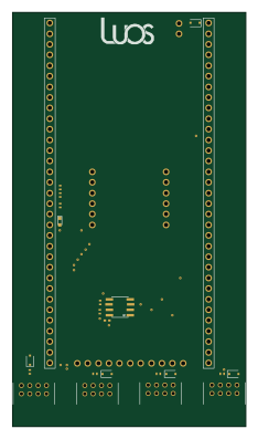
Stm32f0 disco Luos shield
55.9 × 99.1 mm26 parts2LMIT547
L0 USBA
20.3 × 15.3 mm19 parts2LMIT547