
Dc power monitor

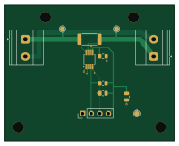
About the Dc power monitor PCB
Dc power monitor is an open source RP2040/RP2350 PCB design by seanahuynh, published on GitHub. It is a 2-layer board measuring 50 × 40 mm, with 9 components from 8 distinct parts.
Its main chip is the PICO I2C / 3.3V, from the RP2040/RP2350 family. Other key parts include the INA226AIDGSR. By type, the board carries 3 connectors, 3 resistors, 2 capacitors and 1 IC.
From the project
0–12 V, 1 A DC power monitor with a custom KiCad PCB, Raspberry Pi Pico firmware, Python logging, calibration tools, and bench-test documentation. Unbuilt prototype.
A student hardware project: design, assemble, calibrate, and characterize a USB-connected DC power monitor. Revision A measures a 0–12 V, 0–1 A DC load using a custom INA226 PCB and an external Raspberry Pi Pico H. Firmware streams nominally 10 readings/s; the Python logger saves raw data, calibrated CSV, energy estimates, and an HTML plot.
Status: CAD and software validated; physical prototype not assembled or tested. Demo plots are synthetic. See checks/release-validation.json for the generated release checks, and docs/TEST-PLAN.md for the measurements still needed.
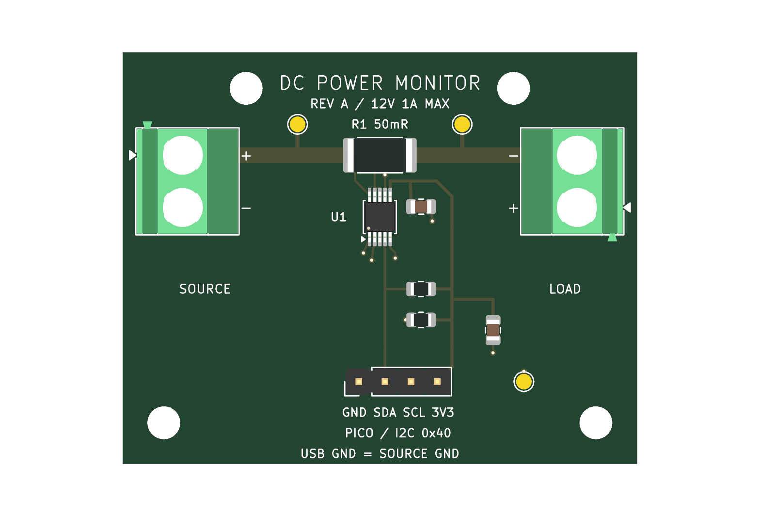
Main components on the Dc power monitor
Dc power monitor bill of materials (BOM)
9 components, 8 distinct parts — part numbers from the project's BOM.
| Qty | Part | Footprint | Refs |
|---|---|---|---|
| 1 | INA226AIDGSR | MSOP-10_3x3mm_P0.5mm | U1 |
| 1 | SOURCE 0-12V | TerminalBlock_Phoenix_MKDS-1,5-2-5.08_1x02_P5.08mm_Horizontal | J1 |
| 1 | LOAD 1A MAX | TerminalBlock_Phoenix_MKDS-1,5-2-5.08_1x02_P5.08mm_Horizontal | J2 |
| 1 | PICO I2C / 3.3V | PinHeader_1x04_P2.54mm_Vertical | J3 |
| 1 | 100nF 16V X7R | C_0805_2012Metric | C1 |
| 1 | 1uF 16V X7R | C_0805_2012Metric | C2 |
| 1 | 0.050 ohm 1% 1W | R_2512_6332Metric | R1 |
| 2 | 4.7k 1% | R_0805_2012Metric | R2, R3 |
Dc power monitor design files
The KiCad project lives in the seanahuynh/dc-power-monitor repository on GitHub; these links point at the commit this page was built from.
- LayoutDC-Power-Monitor.kicad_pcb
- SchematicDC-Power-Monitor.kicad_sch
- BOMBOM.csv
Dc power monitor: common questions
What microcontroller does the Dc power monitor use?
The Dc power monitor is built around the PICO I2C / 3.3V, from the RP2040/RP2350 family.
How big is the Dc power monitor PCB?
The Dc power monitor measures 50 × 40 mm, has 2 copper layers and is 1.6 mm thick.
How many components are on the Dc power monitor?
9 components, from 8 distinct parts, with part numbers taken from the project's own BOM. The full bill of materials is listed on this page.
Where can I download the Dc power monitor design files?
From the seanahuynh/dc-power-monitor repository on GitHub, which has the KiCad layout, the schematic and the BOM; the links under Design files point to each one.
Can I use the Dc power monitor design in my own project?
The repository has no license, so all rights stay with seanahuynh. Use it as a reference, and ask the author before reusing the design.
Can I test firmware for the Dc power monitor without the hardware?
Yes. HardLabs builds a simulation of the board from its netlist and BOM, so you can run and debug RP2040/RP2350 firmware against it before you order a PCB.
Similar boards
 RP2040/RP2350
Open Book Abridged Edition
joeycastillo
85 × 115 mm29 parts2LCC-BY-SA-4.08.1k RP2040/RP2350
Corne
foostan
277.2 × 107.5 mm164 parts2LCC-BY-4.07.7k RP2040/RP2350
Corne
277.2 × 107.5 mm164 parts2LCC-BY-4.07.7k RP2040/RP2350
LogicAnalyzer
gusmanb
57 × 55.2 mm6 parts2LGPL-3.05.0k RP2040/RP2350
Jitx design
55.5 × 65 mm26 parts4LGPL-3.05.0k RP2040/RP2350
Main
google
98 × 71 mm102 parts2LApache-2.02.9k