
Digitally-Controlled-Mixed-Signal-Power-Supply-

About the Digitally-Controlled-Mixed-Signal-Power-Supply- PCB
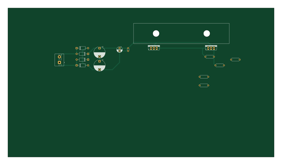
Digitally-Controlled-Mixed-Signal-Power-Supply- is an open source AVR/Arduino PCB design by shubham7547, published on GitHub. It is a 2-layer board measuring 236.2 × 132.1 mm, with 50 components from 34 distinct parts.
Its main chip is the Arduino_Nano_Every, from the AVR/Arduino family. Other key parts include the CR2013-MI2120 and TLC5618AQD. By type, the board carries 16 resistors, 11 capacitors, 8 diodes, 3 ICs, 2 transistors and 2 inductors.
It belongs with the power & battery designs in this gallery.
From the project
A high-performance, digitally controlled benchtop power supply that bridges digital precision with an ultra-fast analog regulation loop. The system delivers an adjustable 0 to 30.0 V output at up to 1.0 A, featuring dual rotary quadrature encoders with digit-level selection, high
A high-performance, digitally controlled benchtop power supply that bridges digital precision with an ultra-fast analog regulation loop. The system delivers an adjustable 0 to 30.0 V output at up to 1.0 A, featuring dual rotary quadrature encoders with digit-level selection, high-resolution readbacks on a 2.8" color TFT display, and a non-blocking embedded firmware architecture.
Main components on the Digitally-Controlled-Mixed-Signal-Power-Supply-
Digitally-Controlled-Mixed-Signal-Power-Supply- bill of materials (BOM)
50 components, 34 distinct parts.
| Qty | Part | Footprint | Refs |
|---|---|---|---|
| 1 | ~ | DIL08 | IC1 |
| 1 | CR2013-MI2120 | CR2013-MI2120 | U1 |
| 1 | TLC5618AQD | BOB | U2 |
| 1 | Arduino_Nano_Every | Arduino_Nano | A1 |
| 2 | MJE3055 | TO220AV | Q1, Q2 |
| 1 | Screw_Terminal_01x02 | TerminalBlock_MaiXu_MX126-5.0-02P_1x02_P5.00mm | J1 |
| 3 | Heatsink | HEATSINK | HS1, HS2, HS3 |
| 1 | Transformer_1P_1S | TerminalBlock_MaiXu_MX126-5.0-02P_1x02_P5.00mm | T1 |
| 2 | ~ | TO170P1067X483X1651-5 | VR5, VR6 |
| 4 | D_45deg_Filled | D_A-405_P10.16mm_Horizontal | D1, D2, D3, D4 |
| 2 | ~ | DO41-10 | D8, D9 |
| 2 | LED | LED_D5.0mm | D10, D11 |
| 1 | 470uH | L_Radial_D7.0mm_P3.00mm | L4 |
| 1 | 100uH | L_Radial_D7.0mm_P3.00mm | L5 |
| 1 | C | C_Disc_D3.0mm_W1.6mm_P2.50mm | C1 |
| 2 | 4700uF | CP_Radial_D10.0mm_P7.50mm | C2, C4 |
| 1 | 0.1u | C_Disc_D3.0mm_W1.6mm_P2.50mm | C3 |
| 1 | 470uF | CP_Radial_D5.0mm_P2.50mm | C5 |
| 1 | 100nF | CP_Radial_D5.0mm_P2.50mm | C6 |
| 1 | 10uF | CP_Radial_D5.0mm_P2.50mm | C7 |
Show 14 more
| Qty | Part | Footprint | Refs |
|---|---|---|---|
| 2 | 100uF | CP_Radial_D5.0mm_P2.50mm | C8, C10 |
| 2 | 1000uF | CP_Radial_D8.0mm_P5.00mm | C9, C11 |
| 1 | 4.7K | R_Axial_DIN0207_L6.3mm_D2.5mm_P7.62mm_Horizontal | R1 |
| 1 | 220 | R_Axial_DIN0207_L6.3mm_D2.5mm_P7.62mm_Horizontal | R2 |
| 1 | 0.3 | R_Axial_DIN0207_L6.3mm_D2.5mm_P7.62mm_Horizontal | R3 |
| 1 | 46k | R_Axial_DIN0207_L6.3mm_D2.5mm_P7.62mm_Horizontal | R4 |
| 3 | 2.2K | R_Axial_DIN0207_L6.3mm_D2.5mm_P7.62mm_Horizontal | R5, R8, R9 |
| 2 | 1K | R_Axial_DIN0207_L6.3mm_D2.5mm_P7.62mm_Horizontal | R6, R7 |
| 1 | 470 | R_Axial_DIN0207_L6.3mm_D2.5mm_P7.62mm_Horizontal | R10 |
| 1 | 47k | R_Axial_DIN0204_L3.6mm_D1.6mm_P7.62mm_Horizontal | R11 |
| 1 | 1.5k | R_Axial_DIN0204_L3.6mm_D1.6mm_P7.62mm_Horizontal | R12 |
| 1 | 3.3K | R_Axial_DIN0204_L3.6mm_D1.6mm_P7.62mm_Horizontal | R13 |
| 2 | 330 | R_Axial_DIN0204_L3.6mm_D1.6mm_P7.62mm_Horizontal | R14, R16 |
| 1 | 1K | R_Axial_DIN0204_L3.6mm_D1.6mm_P7.62mm_Horizontal | R15 |
Digitally-Controlled-Mixed-Signal-Power-Supply- design files
The KiCad project lives in the shubham7547/Digitally-Controlled-Mixed-Signal-Power-Supply- repository on GitHub; these links point at the commit this page was built from.
Digitally-Controlled-Mixed-Signal-Power-Supply-: common questions
What microcontroller does the Digitally-Controlled-Mixed-Signal-Power-Supply- use?
The Digitally-Controlled-Mixed-Signal-Power-Supply- is built around the Arduino_Nano_Every, from the AVR/Arduino family.
How big is the Digitally-Controlled-Mixed-Signal-Power-Supply- PCB?
The Digitally-Controlled-Mixed-Signal-Power-Supply- measures 236.2 × 132.1 mm, has 2 copper layers and is 1.6 mm thick.
How many components are on the Digitally-Controlled-Mixed-Signal-Power-Supply-?
50 components, from 34 distinct parts. The full bill of materials is listed on this page.
Where can I download the Digitally-Controlled-Mixed-Signal-Power-Supply- design files?
From the shubham7547/Digitally-Controlled-Mixed-Signal-Power-Supply- repository on GitHub, which has the KiCad layout and the schematic; the links under Design files point to each one.
Can I use the Digitally-Controlled-Mixed-Signal-Power-Supply- design in my own project?
The repository has no license, so all rights stay with shubham7547. Use it as a reference, and ask the author before reusing the design.
Can I test firmware for the Digitally-Controlled-Mixed-Signal-Power-Supply- without the hardware?
Yes. HardLabs builds a simulation of the board from its netlist and BOM, so you can run and debug AVR/Arduino firmware against it before you order a PCB.
Similar boards
 AVR/Arduino
Magspoof
samyk
35 × 29 mm11 parts2LNo license4.2k AVR/Arduino
Redox keyboard
mattdibi
162.2 × 126.5 mm77 parts2LMIT2.0k AVR/Arduino
Labrador
espotek-org
36.8 × 34.7 mm75 parts2LNo license1.2k AVR/Arduino
ModuleV450
stuartpittaway
30 × 61.4 mm39 parts2LCC-BY-NC-4.01.1k AVR/Arduino
V4
30 × 50 mm38 parts2LCC-BY-NC-4.01.1k AVR/Arduino
Discipline
coseyfannitutti
304.9 × 122.8 mm170 parts2LCC-BY-NC-4.01.0k