
Basic stepper driver hardware design

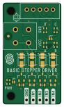
About the Basic stepper driver hardware design PCB
Basic stepper driver hardware design is an open source PCB design by SolderedElectronics, published on GitHub under the TAPR-OHL-1.0 license. It is a 2-layer board measuring 22 × 38 mm, with 29 components from 12 distinct parts.
By type, the board carries 9 diodes, 9 resistors, 4 transistors, 3 relays and 2 jumpers.
It belongs with the robotics & motion designs in this gallery.
From the project
Hardware design, BOM, gerbers and 3D files for Basic-stepper-driver designed by Soldered Electronics.
This driver for stepper motor enables control over a stepper motor that does not require more than 800mA of current and works at up to 14V voltage. Except for the driver, it has built-in LED lights that indicate which phase of the motor is currently active. Connecting with microcontroller is easy, and control is directly through the library.
This repository contains all design files for Basic stepper driver, organized as follows:

Basic stepper driver hardware design bill of materials (BOM)
29 components, 12 distinct parts — part numbers from the project's BOM.
| Qty | Part | Footprint | Refs |
|---|---|---|---|
| 4 | NPN-SOT-23-3 | SOT-23-3 | Q1, Q2, Q3, Q4 |
| 2 | HOLE_3.2mm | HOLE_3.2mm | H1, H2 |
| 1 | SMD-JUMPER-CONNECTED_TRACE_SLODERMASK | SMD-JUMPER-CONNECTED_TRACE_SLODERMASK | JP1 |
| 1 | SMD_JUMPER | SMD_JUMPER | JP2 |
| 1 | TERMINAL_KF235-5.0-2P | TERMINAL_KF235-5.0-2P | K1 |
| 1 | HEADER_MALE_5X1 | HEADER_MALE_5X1 | K2 |
| 1 | JST_XH_5A_CONNECTOR | JST_XH_5A_CONNECTOR | K3 |
| 1 | purple | 0402LED | D1 |
| 4 | M4_DIODA | M4_DIODA | D2, D7, D8, D9 |
| 4 | green | 0402LED | D3, D4, D5, D6 |
| 5 | 2k2 | 0402R | R1, R3, R4, R5, R6 |
| 4 | 1k | 0603R | R2, R7, R8, R9 |
Basic stepper driver hardware design design files
The KiCad project lives in the SolderedElectronics/Basic-stepper-driver-hardware-design repository on GitHub; these links point at the commit this page was built from.
Basic stepper driver hardware design: common questions
How big is the Basic stepper driver hardware design PCB?
The Basic stepper driver hardware design measures 22 × 38 mm, has 2 copper layers and is 1.6 mm thick.
How many components are on the Basic stepper driver hardware design?
29 components, from 12 distinct parts, with part numbers taken from the project's own BOM. The full bill of materials is listed on this page.
Where can I download the Basic stepper driver hardware design design files?
From the SolderedElectronics/Basic-stepper-driver-hardware-design repository on GitHub, which has the KiCad layout, the schematic and the BOM; the links under Design files point to each one.
Can I use the Basic stepper driver hardware design design in my own project?
Yes, under the terms of its TAPR-OHL-1.0 license, which SolderedElectronics chose for the repository.
Similar boards

Cube batteryboard
willem-pennings
95 × 95 mm4 parts2LGPL-3.01.1k
Rp2040 encoder
Twisted-Fields
36.7 × 33.3 mm10 parts2LCustom license417
VESC Controller
paltatech
160 × 90 mm908 parts2LNo license354
${BOARD NAME} Assembly
EPFLXplore
45 × 43.5 mm21 parts4LApache-2.0345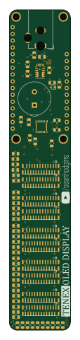
Volumetric display
idlehandsdev
23 × 120 mm70 parts2LCC-BY-SA-4.0312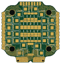
OpenESC-20x20
OpenDrone-hw
31.2 × 33 mm180 parts6LCERN-OHL-S-2.0243