
LIN-Transceiver-NCV7329-SLAVE-breakout hardware design

About the LIN-Transceiver-NCV7329-SLAVE-breakout hardware design
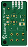
LIN-Transceiver-NCV7329-SLAVE-breakout hardware design is an open source PCB design by SolderedElectronics, published on GitHub under the TAPR-OHL-1.0 license. It is a 2-layer board measuring 22 × 38 mm, with 14 components from 12 distinct parts.
Other key parts include the NCV7329. By type, the board carries 3 diodes, 3 resistors, 2 relays, 2 capacitors, 1 IC and 1 jumper.
It belongs with the rf & radio and dev boards & breakouts designs in this gallery.
From the project
Hardware design, BOM, gerbers and 3D files for LIN-Transceiver-NCV7329-SLAVE-breakout designed by Soldered Electronics.
LIN (Local Interconnect Network) is a serial network protocol used for communication between components in cars. The LIN bus is an alternative to the CAN bus, and the difference is that LIN has a lower speed and supports a smaller number of simultaneous devices, but also has drastically lower costs. LIN is used for communication between microcontrollers. The operating voltage is 18V.

Main components on the LIN-Transceiver-NCV7329-SLAVE-breakout hardware design
LIN-Transceiver-NCV7329-SLAVE-breakout hardware design bill of materials (BOM)
14 components, 12 distinct parts — part numbers from the project's BOM.
| Qty | Part | Footprint | Refs |
|---|---|---|---|
| 1 | NCV7329 | SOIC−8 | U1 |
| 2 | HOLE_3.2mm | HOLE_3.2mm | H1, H2 |
| 1 | SMD-JUMPER-CONNECTED_TRACE_SLODERMASK | SMD-JUMPER-CONNECTED_TRACE_SLODERMASK | JP1 |
| 1 | HEADER_MALE_4X1 | HEADER_MALE_4X1 | K1 |
| 1 | TERMINAL_KF235-5.0-3P | TERMINAL_KF235-5.0-3P | K2 |
| 2 | M4_DIODA | M4_DIODA | D1, D3 |
| 1 | purple | 0402LED | D2 |
| 1 | 2.2uF | 0603C | C1 |
| 1 | 270pF | 0603C | C2 |
| 1 | 4.7k | 0603R | R1 |
| 1 | 2k2 | 0402R | R2 |
| 1 | 1k | 0603R | R3 |
LIN-Transceiver-NCV7329-SLAVE-breakout hardware design design files
The KiCad project lives in the SolderedElectronics/LIN-Transceiver-NCV7329-SLAVE-breakout-hardware-design repository on GitHub; these links point at the commit this page was built from.
LIN-Transceiver-NCV7329-SLAVE-breakout hardware design: common questions
How big is the LIN-Transceiver-NCV7329-SLAVE-breakout hardware design?
The LIN-Transceiver-NCV7329-SLAVE-breakout hardware design measures 22 × 38 mm, has 2 copper layers and is 1.6 mm thick.
How many components are on the LIN-Transceiver-NCV7329-SLAVE-breakout hardware design?
14 components, from 12 distinct parts, with part numbers taken from the project's own BOM. The full bill of materials is listed on this page.
Where can I download the LIN-Transceiver-NCV7329-SLAVE-breakout hardware design design files?
From the SolderedElectronics/LIN-Transceiver-NCV7329-SLAVE-breakout-hardware-design repository on GitHub, which has the KiCad layout, the schematic and the BOM; the links under Design files point to each one.
Can I use the LIN-Transceiver-NCV7329-SLAVE-breakout hardware design design in my own project?
Yes, under the terms of its TAPR-OHL-1.0 license, which SolderedElectronics chose for the repository.
Similar boards

Radioberry juice
pa3gsb
65 × 56 mm87 parts2LNo license675
Radioberry preamp
65 × 56 mm137 parts2LNo license675
Hat
65 × 56 mm81 parts2LNo license675
Sram dev board
Wren6991
50 × 50 mm12 parts2LNo license508
ESP32
Chrismettal
66.4 × 48.1 mm20 parts2LCC-BY-SA-4.0446
ESP32
66.4 × 48.1 mm20 parts2LCC-BY-SA-4.0446