
RS-232-Transceiver breakout hardware design

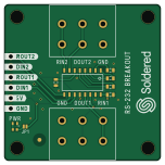
About the RS-232-Transceiver breakout hardware design
RS-232-Transceiver breakout hardware design is an open source PCB design by SolderedElectronics, published on GitHub under the TAPR-OHL-1.0 license. It is a 2-layer board measuring 38 × 38 mm, with 16 components from 8 distinct parts.
Other key parts include the MAX232ECD. By type, the board carries 5 capacitors, 3 relays, 1 IC, 1 jumper, 1 diode and 1 resistor.
It belongs with the rf & radio and dev boards & breakouts designs in this gallery.
From the project
Hardware design, BOM, gerbers and 3D files for RS-232-Transceiver-breakout designed by Soldered Electronics.
The RS-232 is a standard and very popular protocol for communication between two devices. It is a full-duplex protocol which means it can receive and send data at the same time, and data is sent at voltages from + 3V to + 15V for a digital “one” and from -3V to -15V for digital “zero”. This provides a more secure environment for data transmission which is resistant to noise or interference, which is why the RS-232 is often used in industry. This module converts serial communication to RS232.

Main components on the RS-232-Transceiver breakout hardware design
RS-232-Transceiver breakout hardware design bill of materials (BOM)
16 components, 8 distinct parts — part numbers from the project's BOM.
| Qty | Part | Footprint | Refs |
|---|---|---|---|
| 1 | MAX232ECD | SOP-16 | U1 |
| 4 | HOLE_3.2mm | HOLE_3.2mm | H1, H2, H3, H4 |
| 1 | SMD-JUMPER-CONNECTED_TRACE_SLODERMASK | SMD-JUMPER-CONNECTED_TRACE_SLODERMASK | JP1 |
| 2 | TERMINAL_KF235-5.0-3P | TERMINAL_KF235-5.0-3P | K1, K2 |
| 1 | HEADER_MALE_6X1 | HEADER_MALE_6X1 | K3 |
| 1 | purple | 0402LED | D1 |
| 5 | 4u7 | 0603C | C1, C2, C3, C4, C5 |
| 1 | 2k2 | 0402R | R1 |
RS-232-Transceiver breakout hardware design design files
The KiCad project lives in the SolderedElectronics/RS-232-Transceiver-breakout-hardware-design repository on GitHub; these links point at the commit this page was built from.
RS-232-Transceiver breakout hardware design: common questions
How big is the RS-232-Transceiver breakout hardware design?
The RS-232-Transceiver breakout hardware design measures 38 × 38 mm, has 2 copper layers and is 1.6 mm thick.
How many components are on the RS-232-Transceiver breakout hardware design?
16 components, from 8 distinct parts, with part numbers taken from the project's own BOM. The full bill of materials is listed on this page.
Where can I download the RS-232-Transceiver breakout hardware design design files?
From the SolderedElectronics/RS-232-Transceiver-breakout-hardware-design repository on GitHub, which has the KiCad layout, the schematic and the BOM; the links under Design files point to each one.
Can I use the RS-232-Transceiver breakout hardware design design in my own project?
Yes, under the terms of its TAPR-OHL-1.0 license, which SolderedElectronics chose for the repository.
Similar boards

Radioberry juice
pa3gsb
65 × 56 mm87 parts2LNo license675
Radioberry preamp
65 × 56 mm137 parts2LNo license675
Hat
65 × 56 mm81 parts2LNo license675
Sram dev board
Wren6991
50 × 50 mm12 parts2LNo license508
ESP32
Chrismettal
66.4 × 48.1 mm20 parts2LCC-BY-SA-4.0446
ESP32
66.4 × 48.1 mm20 parts2LCC-BY-SA-4.0446