
Embedded debug

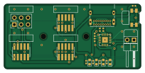
About the Embedded debug PCB
Embedded debug is an open source PCB design by stephendpmurphy, published on GitHub under the CC-BY-SA-4.0 license. It is a 2-layer board measuring 50.8 × 24.1 mm, with 21 components from 11 distinct parts.
Other key parts include the FT230XQ. By type, the board carries 7 resistors, 6 connectors, 4 diodes, 2 capacitors, 1 IC and 1 switch.
It belongs with the usb & debug tools designs in this gallery.
From the project
The embedded debug board can be used to provide access to Target MCU debug UART lines carried on unused traces of a 10pin SWD connector
This debug board allows two unused traces of a 10pin (1.27mm pitch) connector to be broken out and used for a UART RX & TX line from the target MCU. These UART lines can be used by the Target to send debug print statements through the programming connector, to the USB bridge, and then displayed on a PC terminal. This is useful since board space is no longer needed on the target for any sort of extra headers or test pads for debug data.
Main components on the Embedded debug
Embedded debug bill of materials (BOM)
21 components, 11 distinct parts.
| Qty | Part | Footprint | Refs |
|---|---|---|---|
| 1 | FT230XQ | QFN-16-1EP_4x4mm_P0.65mm_EP2.1x2.1mm | U1 |
| 3 | Conn_02x05_Odd_Even | PinHeader_2x05_P1.27mm_Vertical_SMD | J1, J2, J6 |
| 1 | Conn_01x02 | PinHeader_1x02_P2.54mm_Horizontal | J3 |
| 1 | USB_C_Receptacle_USB2.0 | USB_C_Receptacle_GCT_USB4085 | J4 |
| 1 | AVR-ISP-6 | PinHeader_2x03_P2.54mm_Vertical | J5 |
| 1 | SW_Push | Panasonic_EVQPUJ_EVQPUA | SW1 |
| 4 | LED | LED_0603_1608Metric | D1, D2, D3, D4 |
| 2 | .1u | C_0402_1005Metric | C1, C2 |
| 2 | 27 | R_0402_1005Metric | R1, R2 |
| 1 | 10k | R_0402_1005Metric | R3 |
| 4 | 1k | R_0402_1005Metric | R4, R5, R6, R7 |
Embedded debug design files
The KiCad project lives in the stephendpmurphy/embedded-debug repository on GitHub; these links point at the commit this page was built from.
Embedded debug: common questions
How big is the Embedded debug PCB?
The Embedded debug measures 50.8 × 24.1 mm, has 2 copper layers and is 1.6 mm thick.
How many components are on the Embedded debug?
21 components, from 11 distinct parts. The full bill of materials is listed on this page.
Where can I download the Embedded debug design files?
From the stephendpmurphy/embedded-debug repository on GitHub, which has the KiCad layout; the links under Design files point to each one.
Can I use the Embedded debug design in my own project?
Yes, under the terms of its CC-BY-SA-4.0 license, which stephendpmurphy chose for the repository.
Similar boards
XG Station Power
osy
54.3 × 91 mm9 parts2LCC-BY-4.0703
USB Hub Test
50 × 50 mm85 parts4LCC-BY-4.0703
FW-EC-DongleHiderPlus
LeoDJ
28.2 × 26.1 mm14 parts4LCERN-OHL-W-2.0490
Adapter tsop48
bbogush
48 × 33 mm3 parts2LGPL-3.0389
Adapter tsop48 solder
48 × 33 mm3 parts2LGPL-3.0389
Adapter soic8 solder
48 × 20 mm3 parts2LGPL-3.0389