
AI Self-Balance Robot

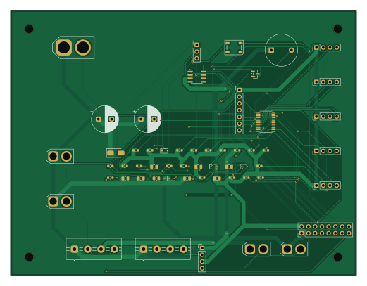
About the AI Self-Balance Robot PCB
AI Self-Balance Robot is an open source STM32 PCB design by SteveZC8537, published on GitHub under the CC-BY-SA-4.0 license. It is a 2-layer board measuring 130 × 100 mm, with 56 components from 34 distinct parts.
Its main chip is the J_MCU ->STM32G474, from the STM32 family. Other key parts include the SN65HVD230 and TCA9548APWR. By type, the board carries 17 resistors, 16 connectors, 13 capacitors, 6 diodes, 2 ICs and 1 transistor.
It belongs with the robotics & motion designs in this gallery.
From the project
全程代码生成 + 命令行(无 GUI 点选),可复现。原理图 → 布局 → 布线 → Gerber。
全程代码生成 + 命令行(无 GUI 点选),可复现。原理图 → 布局 → 布线 → Gerber。
- 45A VBAT/GND 不走线,走整面覆铜(IPC-2221:45A@2oz 需 28.8mm 线宽 → 不现实)。见 功率/热分析。 - 无有源反接保护(LTC4359 在审计中发现会上电死锁)→ keyed XT60 + 外部保险/急停。见 审计。 - 接线/引脚定义见 接线速查;电流/续航见 powerbudget.py`。
ERC 0 错 · DRC 0 unconnected(库/丝印 warnings 豁免)· Gerber 已导出。JLCPCB DFM 待实物下单时跑通存档(审计退出条件 ⑥)——在此之前不称"可下单"。
Main components on the AI Self-Balance Robot
AI Self-Balance Robot bill of materials (BOM)
56 components, 34 distinct parts — part numbers from the project's BOM.
| Qty | Part | Footprint | Refs |
|---|---|---|---|
| 1 | SN65HVD230 | SOIC-8_3.9x4.9mm_P1.27mm | U1 |
| 1 | TCA9548APWR | TSSOP-24_4.4x7.8mm_P0.65mm | U2 |
| 1 | MMBT3904 | SOT-23 | Q1 |
| 1 | J_BAT XT60(经开关/急停/保险) | AMASS_XT60-F_1x02_P7.20mm_Vertical | J1 |
| 1 | J_M1 C620-1 | AMASS_XT30U-F_1x02_P5.0mm_Vertical | J2 |
| 1 | J_M2 C620-2 | AMASS_XT30U-F_1x02_P5.0mm_Vertical | J3 |
| 1 | J_BUCK12 22V->12V/15A | TerminalBlock_MaiXu_MX126-5.0-04P_1x04_P5.00mm | J4 |
| 1 | J_BUCK5 22V->5V/6A | TerminalBlock_MaiXu_MX126-5.0-04P_1x04_P5.00mm | J5 |
| 1 | J_BUCK33 22V->3V3/1A | PinHeader_1x04_P2.54mm_Vertical | J6 |
| 1 | J_SERVO 12V->舵机适配器 | AMASS_XT30U-F_1x02_P5.0mm_Vertical | J7 |
| 1 | J_SBC 5V->Rock5B+ | AMASS_XT30U-F_1x02_P5.0mm_Vertical | J8 |
| 1 | J_CAN ->C620 | PinHeader_1x03_P2.54mm_Vertical | J9 |
| 1 | J_TOF1 VL53L1X | PinHeader_1x04_P2.54mm_Vertical | J10 |
| 1 | J_TOF2 VL53L1X | PinHeader_1x04_P2.54mm_Vertical | J11 |
| 1 | J_TOF3 VL53L1X | PinHeader_1x04_P2.54mm_Vertical | J12 |
| 1 | J_TOF4 VL53L1X | PinHeader_1x04_P2.54mm_Vertical | J13 |
| 1 | J_TOF5 VL53L1X | PinHeader_1x04_P2.54mm_Vertical | J14 |
| 1 | J_IMU ICM-42688 | PinHeader_1x07_P2.54mm_Vertical | J15 |
| 1 | J_MCU ->STM32G474 | PinHeader_2x08_P2.54mm_Vertical | J16 |
| 1 | Buzzer 5V | Buzzer_12x9.5RM7.6 | BZ1 |
Show 14 more
| Qty | Part | Footprint | Refs |
|---|---|---|---|
| 1 | SMAJ33A | D_SMA | D1 |
| 2 | CAN ESD 24V | D_SOD-323 | D2, D3 |
| 1 | 1N4148(降 VDD~4.4V 配 3.3V DIN) | D_SOD-323 | D4 |
| 1 | WS2812B | LED_WS2812B_PLCC4_5.0x5.0mm_P3.2mm | D5 |
| 1 | 1N4148 | D_SOD-323 | D6 |
| 2 | 470uF/35V | CP_Radial_D10.0mm_P5.00mm | C1, C2 |
| 4 | 1uF/50V | C_0805_2012Metric | C3, C4, C5, C6 |
| 3 | 10uF | C_0805_2012Metric | C7, C8, C11 |
| 4 | 100n | C_0603_1608Metric | C9, C10, C12, C13 |
| 1 | 120 | R_0805_2012Metric | R1 |
| 2 | 10k | R_0603_1608Metric | R2, R17 |
| 12 | 4.7k | R_0603_1608Metric | R3, R4, R5, R6, R7, R8, R9, R10 +4 |
| 1 | 1k | R_0603_1608Metric | R15 |
| 1 | 100k | R_0603_1608Metric | R16 |
AI Self-Balance Robot design files
The KiCad project lives in the SteveZC8537/AI_Self-Balance_Robot repository on GitHub; these links point at the commit this page was built from.
AI Self-Balance Robot: common questions
What microcontroller does the AI Self-Balance Robot use?
The AI Self-Balance Robot is built around the J_MCU ->STM32G474, from the STM32 family.
How big is the AI Self-Balance Robot PCB?
The AI Self-Balance Robot measures 130 × 100 mm, has 2 copper layers and is 1.6 mm thick.
How many components are on the AI Self-Balance Robot?
56 components, from 34 distinct parts, with part numbers taken from the project's own BOM. The full bill of materials is listed on this page.
Where can I download the AI Self-Balance Robot design files?
From the SteveZC8537/AI_Self-Balance_Robot repository on GitHub, which has the KiCad layout and the BOM; the links under Design files point to each one.
Can I use the AI Self-Balance Robot design in my own project?
Yes, under the terms of its CC-BY-SA-4.0 license, which SteveZC8537 chose for the repository.
Can I test firmware for the AI Self-Balance Robot without the hardware?
Yes. HardLabs builds a simulation of the board from its netlist and BOM, so you can run and debug STM32 firmware against it before you order a PCB.
Similar boards
 STM32
STM32LumenPnP Motherboard
opulo-inc
149 × 95 mm296 parts4LCC-BY-SA-4.03.7k STM32
STM32AxxSolder
AxxAxx
39 × 82.5 mm122 parts2LGPL-3.01.7k STM32
STM32LibreVNA
jankae
122 × 98 mm592 parts6LGPL-3.01.6k STM32
STM32AIOC
skuep
21 × 31.5 mm47 parts2LMIT1.4k STM32
STM32Ferris
pierrechevalier83
208.8 × 86.8 mm102 parts2LSHL-2.11.3k STM32
STM32176 pin board
rusefi
61.8 × 73.2 mm76 parts2LGPL-3.01.2k