
USB-TO-EtherCAT-Adapter-Board

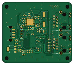
About the USB-TO-EtherCAT-Adapter-Board
USB-TO-EtherCAT-Adapter-Board is an open source STM32 PCB design by Sudeshpandit, published on GitHub. It is a 2-layer board measuring 61 × 53 mm, with 80 components from 31 distinct parts.
Its main chip is the STM32F411CEUx, from the STM32 family. Other key parts include the 24LC512, LAN9252I_ML and AMS1117-3.3. By type, the board carries 35 capacitors, 25 resistors, 5 inductors, 4 ICs, 4 connectors and 3 crystals.
It belongs with the usb & debug tools designs in this gallery.
From the project
Designed a 2-layer PCB that converts USB to EtherCAT for industrial network communication. Worked on the complete design flow — schematic design, component selection, PCB layout, and routing in KiCad. Ran DRC checks to ensure a clean, error-free design.
When I started, I barely knew how a PCB actually gets made — the first few days were confusing, and I kept hitting DRC errors without understanding why. Things started clicking as I worked through mistakes instead of just reading about them.
Over the internship I built up through 14 PCB projects, gaining hands-on experience with STM32 microcontrollers, SPI/I2C communication, and industrial protocols like EtherCAT — along the way strengthening my problem-solving (debugging DRC errors and routing conflicts), documentation, and the discipline of verifying a design before calling it done.
Main components on the USB-TO-EtherCAT-Adapter-Board
USB-TO-EtherCAT-Adapter-Board bill of materials (BOM)
80 components, 31 distinct parts.
| Qty | Part | Footprint | Refs |
|---|---|---|---|
| 1 | STM32F411CEUx | QFN-48-1EP_7x7mm_P0.5mm_EP5.6x5.6mm | U1 |
| 1 | 24LC512 | TSSOP-8_3x3mm_P0.65mm | U2 |
| 1 | LAN9252I_ML | QFN50P900X900X100-65N- | U4 |
| 1 | AMS1117-3.3 | SOT-223-3_TabPin2 | U5 |
| 1 | SF-3215-32.768KHZ | Crystal_SMD_3215-2Pin_3.2x1.5mm | Y1 |
| 2 | HC-49SMD-25Mhz Crystal | Crystal_SMD_HC49-SD | Y2, Y3 |
| 2 | RJ45_Hanrun_HR911105A_Horizontal | RJ45_Hanrun_HR911105A_Horizontal | J1, J2 |
| 1 | USB_A | USB_A_CNCTech_1001-011-01101_Horizontal | J3 |
| 1 | Conn_01x04 | PinHeader_1x04_P2.54mm_Vertical | J5 |
| 1 | SW_Push | SW_SPST_B3U-1000P | SW1 |
| 2 | LED | LED_0603_1608Metric | D1, D3 |
| 1 | ESD9B5.0ST5G | C_0805_2012Metric | D2 |
| 1 | FerriteBead 600R | L_0603_1608Metric | FB1 |
| 4 | BLM18EG221SN1D | L_0603_1608Metric | FB2, FB3, FB4, FB5 |
| 2 | 12uF | C_0603_1608Metric | C1, C2 |
| 4 | 12pF | C_0603_1608Metric | C3, C4, C14, C15 |
| 1 | 2.2uF | C_0805_2012Metric | C5 |
| 2 | 0.022uF | C_0603_1608Metric | C6, C7 |
| 22 | 0.1uF | C_0603_1608Metric | C8, C9, C10, C11, C12, C13, C18, C20 +14 |
| 1 | 10uF | C_0805_2012Metric | C19 |
Show 11 more
| Qty | Part | Footprint | Refs |
|---|---|---|---|
| 1 | 1uF | C_0603_1608Metric | C25 |
| 1 | 0.1uF | C_0805_2012Metric | C26 |
| 1 | 470pF | C_0603_1608Metric | C28 |
| 8 | 49.9R | R_0603_1608Metric | R1, R2, R3, R4, R5, R6, R7, R8 |
| 4 | 0R | R_0603_1608Metric | R9, R11, R12, R13 |
| 3 | 10K | R_0603_1608Metric | R10, R16, R17 |
| 3 | 200R | R_0603_1608Metric | R14, R15, R23 |
| 1 | 220R | R_0603_1608Metric | R18 |
| 3 | 4.7k | R_0603_1608Metric | R19, R21, R22 |
| 1 | 12.1k | R_0603_1608Metric | R20 |
| 2 | 10R | R_0603_1608Metric | R24, R25 |
USB-TO-EtherCAT-Adapter-Board design files
The KiCad project lives in the Sudeshpandit/USB-TO-EtherCAT-Adapter-Board repository on GitHub; these links point at the commit this page was built from.
USB-TO-EtherCAT-Adapter-Board: common questions
What microcontroller does the USB-TO-EtherCAT-Adapter-Board use?
The USB-TO-EtherCAT-Adapter-Board is built around the STM32F411CEUx, from the STM32 family.
How big is the USB-TO-EtherCAT-Adapter-Board?
The USB-TO-EtherCAT-Adapter-Board measures 61 × 53 mm, has 2 copper layers and is 1.6 mm thick.
How many components are on the USB-TO-EtherCAT-Adapter-Board?
80 components, from 31 distinct parts. The full bill of materials is listed on this page.
Where can I download the USB-TO-EtherCAT-Adapter-Board design files?
From the Sudeshpandit/USB-TO-EtherCAT-Adapter-Board repository on GitHub, which has the KiCad layout and the schematic; the links under Design files point to each one.
Can I use the USB-TO-EtherCAT-Adapter-Board design in my own project?
The repository has no license, so all rights stay with Sudeshpandit. Use it as a reference, and ask the author before reusing the design.
Can I test firmware for the USB-TO-EtherCAT-Adapter-Board without the hardware?
Yes. HardLabs builds a simulation of the board from its netlist and BOM, so you can run and debug STM32 firmware against it before you order a PCB.
Similar boards
 STM32
STM32LumenPnP Motherboard
opulo-inc
149 × 95 mm296 parts4LCC-BY-SA-4.03.7k STM32
STM32AxxSolder
AxxAxx
39 × 82.5 mm122 parts2LGPL-3.01.7k STM32
STM32LibreVNA
jankae
122 × 98 mm592 parts6LGPL-3.01.6k STM32
STM32AIOC
skuep
21 × 31.5 mm47 parts2LMIT1.4k STM32
STM32Ferris
pierrechevalier83
208.8 × 86.8 mm102 parts2LSHL-2.11.3k STM32
STM32176 pin board
rusefi
61.8 × 73.2 mm76 parts2LGPL-3.01.2k