
Clock test

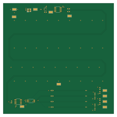
About the Clock test PCB
Clock test is an open source PCB design by tart-telescope, published on GitHub under the GPL-3.0 license. It is a 4-layer board measuring 100 × 100 mm, with 31 components from 16 distinct parts.
Other key parts include the K7805MT-1000R4 and AMS1117-3.3. By type, the board carries 16 resistors, 10 capacitors, 4 ICs and 1 crystal.
It belongs with the rf & radio designs in this gallery.
From the project
Designs for the TART-3 electronics hardware
This folder contains the schematics for the radio module of the TART radio telescope.
Main components on the Clock test
Clock test bill of materials (BOM)
31 components, 16 distinct parts — part numbers from the project's BOM.
| Qty | Part | Footprint | Refs |
|---|---|---|---|
| 1 | K7805MT-1000R4 CS48520S | SOIC-8_3.9x4.9mm_P1.27mm | U1 |
| 1 | K7805MT-1000R4 74LVC1G04SE-7 | SOT-353_SC-70-5 | U2 |
| 1 | K7805MT-1000R4 CDCV304PWR | TSSOP-8_4.4x3mm_P0.65mm | U3 |
| 1 | AMS1117-3.3 CS48520S | SOIC-8_3.9x4.9mm_P1.27mm | U4 |
| 1 | 1XXB16368MBA | OSC-SMD_4P-L2.5-W2.0-BL | X1 |
| 1 | 10U 1nF | C_0402_1005Metric | C1 |
| 2 | 22U 100n | C_0402_1005Metric | C2, C4 |
| 1 | 10U 100n | C_0402_1005Metric | C3 |
| 1 | 10U 100nF | C_0402_1005Metric | C5 |
| 1 | 22U 100nF | C_0402_1005Metric | C6 |
| 2 | 22U 10n | C_0402_1005Metric | C7, C8 |
| 2 | 100N 10n | C_0402_1005Metric | C9, C10 |
| 1 | 39K 1M | R_0603_1608Metric | R1 |
| 2 | 10 | R_0603_1608Metric | R2, R3 |
| 11 | 100 | R_0603_1608Metric | R4, R6, R7, R8, R10, R11, R12, R13 +3 |
| 2 | 39K 100 | R_0603_1608Metric | R5, R9 |
Clock test design files
The KiCad project lives in the tart-telescope/radio_module repository on GitHub; these links point at the commit this page was built from.
Clock test: common questions
How big is the Clock test PCB?
The Clock test measures 100 × 100 mm, has 4 copper layers and is 1.6 mm thick.
How many components are on the Clock test?
31 components, from 16 distinct parts, with part numbers taken from the project's own BOM. The full bill of materials is listed on this page.
Where can I download the Clock test design files?
From the tart-telescope/radio_module repository on GitHub, which has the KiCad layout, the schematic and the BOM; the links under Design files point to each one.
Can I use the Clock test design in my own project?
Yes, under the terms of its GPL-3.0 license, which tart-telescope chose for the repository.
More boards in radio_module
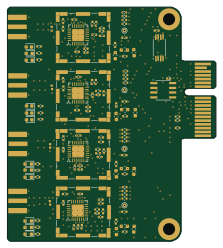
TART Radio Module
55.2 × 62 mm127 parts6LGPL-3.03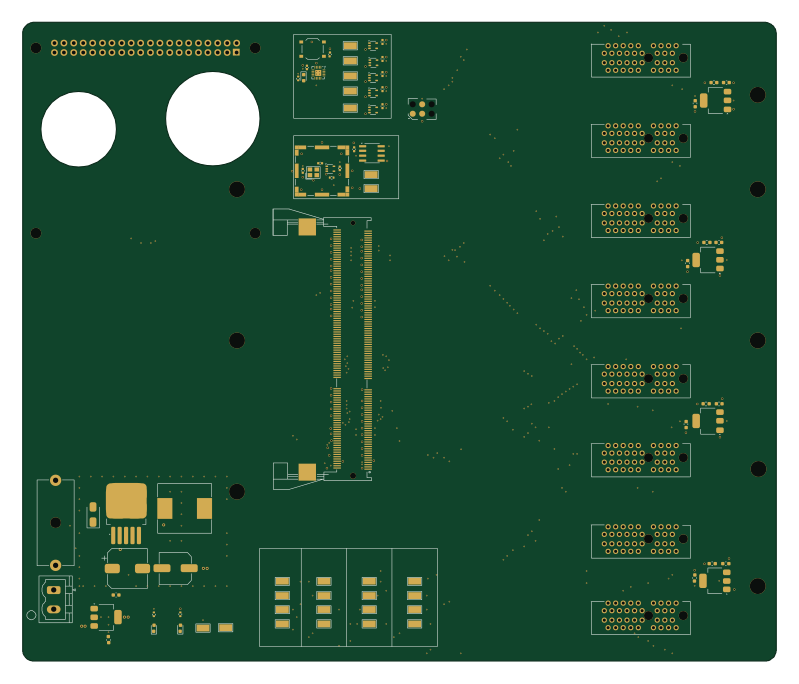 RISC-V
TART3 Motherboard
199.4 × 169 mm89 parts6LGPL-3.03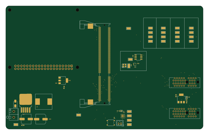 RISC-V
Motherboard 8
168.8 × 105.3 mm57 parts6LGPL-3.03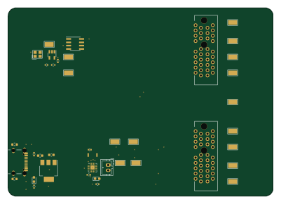 RISC-V
Baseboard
100 × 71 mm40 parts4LGPL-3.03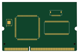
Spartan6 correlator
67.6 × 44.4 mm5 parts2LGPL-3.03
Similar boards

Radioberry preamp
pa3gsb
65 × 56 mm137 parts2LNo license675
Radioberry juice
65 × 56 mm87 parts2LNo license675
Hat
65 × 56 mm81 parts2LNo license675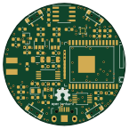
Open smartwatch light
Open-Smartwatch
36.1 × 36.1 mm51 parts4LGPL-3.0246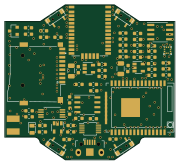
Open smartwatch gps
45 × 41 mm67 parts4LGPL-3.0241
Module17 HMI
M17-Project
97 × 80.9 mm49 parts4LCERN-OHL-W-2.0129