
Orangepi zero3w m2-carrier

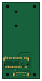
About the Orangepi zero3w m2-carrier PCB
Orangepi zero3w m2-carrier is an open source PCB design by Techburst36, published on GitHub. It is a 2-layer board measuring 32 × 65 mm, with 8 components from 7 distinct parts.
Other key parts include the TPS62086RLTR. By type, the board carries 3 capacitors, 2 connectors, 2 inductors and 1 IC.
It belongs with the dev boards & breakouts designs in this gallery.
From the project
Open-source KiCad design for a PCIe-to-M.2 carrier board for the Orange Pi Zero 3W. Schematic and PCB are ERC/DRC-clean and Gerbers are validated, but PCIe enumeration on this SoC is not yet confirmed. Shared for review, testing, and use by anyone who wants to build on it.
Open-source KiCad design for a PCIe-to-M.2 carrier board for the Orange Pi Zero 3W (Allwinner A733). Breaks out the board's 18-pin PCIe FPC connector to an M.2 M-Key slot for NVMe storage, with an eye toward AI accelerator cards (e.g. Hailo-10H) as a longer-term stretch goal.
- Schematic: complete, ERC-clean (0 errors) - PCB layout: complete, fully routed including differential pairs, DRC-clean (0 errors; remaining warnings are accepted and expected: 0.5mm-pitch connector solder mask clearances, deliberately downgraded to warnings, plus two harmless orphaned-geometry exclusions) - Gerbers…
Main components on the Orangepi zero3w m2-carrier
Orangepi zero3w m2-carrier bill of materials (BOM)
8 components, 7 distinct parts.
| Qty | Part | Footprint | Refs |
|---|---|---|---|
| 1 | TPS62086RLTR | RLT0007A | U1 |
| 1 | 527461870 | CON_527461870_MOL | J1 |
| 1 | MDT670M01501 | AMPHENOL_MDT670M01501 | J2 |
| 1 | CYA0630-1.0UH SHOU HAN(首韩) | IND-SMD_L7.2-W6.6_GPSR0730 | L1 |
| 1 | HCB3216KV-501T30 TAI-TECH(台庆) | L1206 | L2 |
| 2 | CL21A106KAYNNNE SAMSUNG(三星) | CL21A106KAYNNNE_C0805 | C1, C3 |
| 1 | CL21A226MAQNNNE SAMSUNG(三星) | CL21A226MAQNNNE_C0805 | C2 |
Orangepi zero3w m2-carrier design files
The KiCad project lives in the Techburst36/orangepi-zero3w-m2-carrier repository on GitHub; these links point at the commit this page was built from.
Orangepi zero3w m2-carrier: common questions
How big is the Orangepi zero3w m2-carrier PCB?
The Orangepi zero3w m2-carrier measures 32 × 65 mm, has 2 copper layers and is 1.6 mm thick.
How many components are on the Orangepi zero3w m2-carrier?
8 components, from 7 distinct parts. The full bill of materials is listed on this page.
Where can I download the Orangepi zero3w m2-carrier design files?
From the Techburst36/orangepi-zero3w-m2-carrier repository on GitHub, which has the KiCad layout and the schematic; the links under Design files point to each one.
Can I use the Orangepi zero3w m2-carrier design in my own project?
The repository has no license, so all rights stay with Techburst36. Use it as a reference, and ask the author before reusing the design.
Similar boards
88 Pin Vag Breakout
rusefi
142 × 58 mm91 parts2LGPL-3.01.2k
134pin 7-967288-1
139.7 × 73.7 mm38 parts2LGPL-3.01.2k
Breakout 60pin EEC-IV
139.7 × 62.2 mm15 parts2LGPL-3.01.2k
Breakout 112pin Connector
174 × 58 mm39 parts2LGPL-3.01.2k
Eecv breakout
140.8 × 53.7 mm9 parts4LGPL-3.01.2k
Rj45 breakout
rene-dev
15.2 × 53.8 mm3 parts2LGPL-3.0979