
GPIO LCD bench adapter

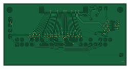
About the GPIO LCD bench adapter PCB
GPIO LCD bench adapter is an open source PCB design by TensorFleet, published on GitHub under the CERN-OHL-S-2.0 license. It is a 4-layer board measuring 63.5 × 32 mm, with 12 components from 10 distinct parts.
Other key parts include the C460313 and TPD2EUSB30DRTR. By type, the board carries 3 ICs, 3 connectors, 2 fuses, 2 capacitors and 2 resistors.
It belongs with the dev boards & breakouts and displays & leds designs in this gallery.
From the project
Modified copy of exentio/koyomi-lvds-hat (CERN-OHL-S-2.0) with a solder mask fix for FL1/FL2
This is the Raspberry Pi 40-pin GPIO addon that drives a separately updated LCD board. It preserves the original A1 in ../gpio-breakout and does not edit any LCD driver or combined-peripheral revision. It is not a carrier-to-carrier adapter, and it is not compatible with the old Hirose LCD board.
J1 is Samtec ZF5S-40-01-T-WT-K-TR (C3169111). Its numbered contacts follow the corrected B2.25 interface: LCD power and GPIO use pins 9–40; ground contacts 5 and 8 also connect to ground. The new USB-C input J3 connects USB supply 1–4, D−6 and D+7. Connect a normal USB-A-to-C cable from the Pi USB…
Main components on the GPIO LCD bench adapter
GPIO LCD bench adapter bill of materials (BOM)
12 components, 10 distinct parts — part numbers from the project's BOM.
| Qty | Part | Footprint | Refs |
|---|---|---|---|
| 1 | C460313 LM66100DCKR | SOT-363_SC-70-6 | U1 |
| 2 | TPD2EUSB30DRTR | Texas_DRT-3 | U2, U3 |
| 1 | ZF5S-40-01-T-WT-K-TR | Samtec_ZF5S-40-01-T-WT_1x40_P0.50mm | J1 |
| 1 | C5311655 Pi GPIO 2x20 | PinHeader_2x20_P2.54mm_Vertical | J2 |
| 1 | 1054500101 Molex | USB_C_Receptacle_Molex_105450-0101 | J3 |
| 1 | 0.5A polyfuse 1206 | Fuse_1206_3216Metric | F1 |
| 1 | SMD1206P050TF/15 | Fuse_1206_3216Metric | F2 |
| 1 | C1592 1u 16V X7R | C_0603_1608Metric | C1 |
| 1 | C1591 100n 16V X7R | C_0603_1608Metric | C2 |
| 2 | C844791 5.1k 1% | R_0603_1608Metric | R1, R2 |
GPIO LCD bench adapter design files
The KiCad project lives in the TensorFleet/koyomi-lvds-hat repository on GitHub; these links point at the commit this page was built from.
GPIO LCD bench adapter: common questions
How big is the GPIO LCD bench adapter PCB?
The GPIO LCD bench adapter measures 63.5 × 32 mm, has 4 copper layers and is 1.6 mm thick.
How many components are on the GPIO LCD bench adapter?
12 components, from 10 distinct parts, with part numbers taken from the project's own BOM. The full bill of materials is listed on this page.
Where can I download the GPIO LCD bench adapter design files?
From the TensorFleet/koyomi-lvds-hat repository on GitHub, which has the KiCad layout, the schematic and the BOM; the links under Design files point to each one.
Can I use the GPIO LCD bench adapter design in my own project?
Yes, under the terms of its CERN-OHL-S-2.0 license, which TensorFleet chose for the repository.
More boards in koyomi-lvds-hat
Similar boards

LevelShifterBreakout
scottbez1
15.2 × 20.3 mm5 parts2LApache-2.022.2k
View base
81.2 × 81.2 mm81 parts2LApache-2.022.2k
View screen
35 × 35 mm12 parts2LApache-2.022.2k
BM28B0.6-24DSBreakout
15.2 × 35.6 mm3 parts2LApache-2.022.2k
ChainlinkDriverTester
198.1 × 95.3 mm123 parts2LApache-2.04.2k
ChainlinkBase
98.4 × 190.5 mm119 parts2LApache-2.04.2k