
RheostatPWM

About the RheostatPWM PCB
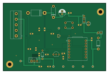
RheostatPWM is an open source RP2040/RP2350 PCB design by TheTinkeringSquid, published on GitHub. It is a 2-layer board measuring 94 × 62 mm, with 29 components from 28 distinct parts.
Its main chip is the XIAO RP2040, from the RP2040/RP2350 family. Other key parts include the Pololu D36V28F5 (off-board, wired). By type, the board carries 11 resistors, 6 diodes, 5 capacitors, 2 ICs, 2 transistors and 1 connector.
It belongs with the test & measurement designs in this gallery.
From the project
PCB to convert an analogue signal from a rheostat into a PWM signal for LEDs
Small RP2040-based PWM dimmer board for a 1996 Dodge B2500 instrument cluster LED conversion. It reads the factory headlight rheostat as an analog input and drives the cluster illumination feed with a protected high-side 12 V PWM output.
The factory rheostat no longer powers the cluster lamps. It is read as a low-current analog control signal through a high-impedance divider into the XIAO RP2040 ADC. Firmware maps that voltage through a gamma curve to a high-side PWM output (P-channel MOSFET Q1 driven by N-MOSFET Q2), so the lamp grounds stay factory.
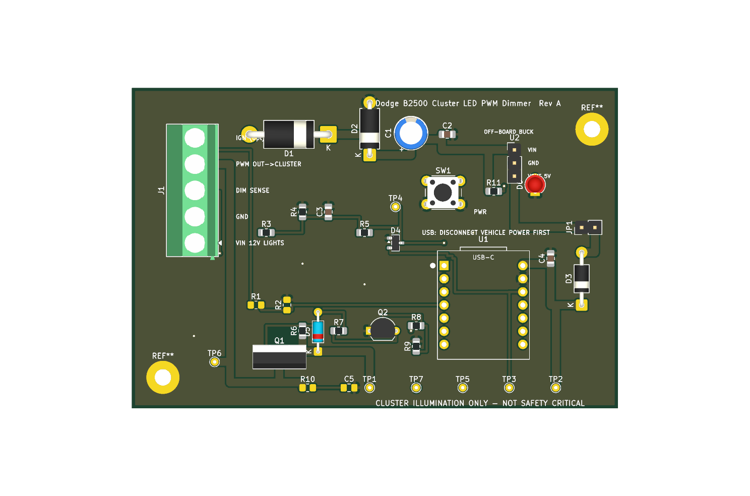
Main components on the RheostatPWM
RheostatPWM bill of materials (BOM)
29 components, 28 distinct parts — part numbers from the project's BOM.
| Qty | Part | Footprint | Refs |
|---|---|---|---|
| 1 | XIAO RP2040 | XIAO_RP2040_THT | U1 |
| 1 | Pololu D36V28F5 (off-board, wired) | PinHeader_1x03_P2.54mm_Vertical | U2 |
| 1 | FQP27P06 | TO-220-3_Vertical | Q1 |
| 1 | 2N7000 | TO-92_Inline_Wide | Q2 |
| 1 | Phoenix MKDS-1,5-5-5.08 | TerminalBlock_Phoenix_MKDS-1,5-5-5.08_1x05_P5.08mm_Horizontal | J1 |
| 1 | 5V_LINK | PinHeader_1x02_P2.54mm_Vertical | JP1 |
| 1 | CAL | SW_PUSH_6mm | SW1 |
| 1 | 1N5822 | D_DO-201AD_P15.24mm_Horizontal | D1 |
| 1 | P6KE24CA | D_DO-15_P10.16mm_Horizontal | D2 |
| 1 | 1N5819 | D_DO-41_SOD81_P10.16mm_Horizontal | D3 |
| 1 | BAT54S | SOT-23 | D4 |
| 1 | 1N5242B 12V | D_DO-35_SOD27_P7.62mm_Horizontal | D5 |
| 1 | Green LED (PWR) | LED_D3.0mm | D6 |
| 1 | 47uF 50V | CP_Radial_D6.3mm_P2.50mm | C1 |
| 1 | 100nF 50V | C_0805_2012Metric_Pad1.18x1.45mm_HandSolder | C2 |
| 1 | 100nF | C_0805_2012Metric_Pad1.18x1.45mm_HandSolder | C3 |
| 1 | 10uF | C_0805_2012Metric_Pad1.18x1.45mm_HandSolder | C4 |
| 1 | 10nF 100V (DNP) | C_0805_2012Metric_Pad1.18x1.45mm_HandSolder | C5 |
| 1 | 100k (DNP) | R_0805_2012Metric_Pad1.20x1.40mm_HandSolder | R1 |
| 1 | 22k (DNP) | R_0805_2012Metric_Pad1.20x1.40mm_HandSolder | R2 |
Show 8 more
| Qty | Part | Footprint | Refs |
|---|---|---|---|
| 1 | 100k 1% | R_0805_2012Metric_Pad1.20x1.40mm_HandSolder | R3 |
| 1 | 22k 1% | R_0805_2012Metric_Pad1.20x1.40mm_HandSolder | R4 |
| 1 | 1k | R_0805_2012Metric_Pad1.20x1.40mm_HandSolder | R5 |
| 1 | 10k | R_0805_2012Metric_Pad1.20x1.40mm_HandSolder | R6 |
| 2 | 100R | R_0805_2012Metric_Pad1.20x1.40mm_HandSolder | R7, R8 |
| 1 | 100k | R_0805_2012Metric_Pad1.20x1.40mm_HandSolder | R9 |
| 1 | 100R (DNP) | R_0805_2012Metric_Pad1.20x1.40mm_HandSolder | R10 |
| 1 | 3.3k | R_0805_2012Metric_Pad1.20x1.40mm_HandSolder | R11 |
RheostatPWM design files
The KiCad project lives in the TheTinkeringSquid/RheostatPWM repository on GitHub; these links point at the commit this page was built from.
RheostatPWM: common questions
What microcontroller does the RheostatPWM use?
The RheostatPWM is built around the XIAO RP2040, from the RP2040/RP2350 family.
How big is the RheostatPWM PCB?
The RheostatPWM measures 94 × 62 mm, has 2 copper layers and is 1.6 mm thick.
How many components are on the RheostatPWM?
29 components, from 28 distinct parts, with part numbers taken from the project's own BOM. The full bill of materials is listed on this page.
Where can I download the RheostatPWM design files?
From the TheTinkeringSquid/RheostatPWM repository on GitHub, which has the KiCad layout, the schematic and the BOM; the links under Design files point to each one.
Can I use the RheostatPWM design in my own project?
The repository has no license, so all rights stay with TheTinkeringSquid. Use it as a reference, and ask the author before reusing the design.
Can I test firmware for the RheostatPWM without the hardware?
Yes. HardLabs builds a simulation of the board from its netlist and BOM, so you can run and debug RP2040/RP2350 firmware against it before you order a PCB.
Similar boards
 RP2040/RP2350
Open Book Abridged Edition
joeycastillo
85 × 115 mm29 parts2LCC-BY-SA-4.08.1k RP2040/RP2350
Corne
foostan
277.2 × 107.5 mm164 parts2LCC-BY-4.07.7k RP2040/RP2350
Corne
277.2 × 107.5 mm164 parts2LCC-BY-4.07.7k RP2040/RP2350
LogicAnalyzer
gusmanb
57 × 55.2 mm6 parts2LGPL-3.05.0k RP2040/RP2350
Jitx design
55.5 × 65 mm26 parts4LGPL-3.05.0k RP2040/RP2350
Pro V2
kata0510
290.1 × 130 mm270 parts2LMIT2.3k