
Amper

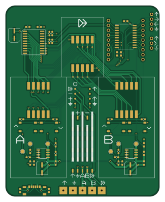
About the Amper PCB
Amper is an open source AVR/Arduino PCB design by Threadnaught, published on GitHub under the GPL-3.0 license. It is a 2-layer board measuring 80 × 99 mm, with 54 components from 28 distinct parts.
Its main chip is the ATtiny1606-S, from the AVR/Arduino family. Other key parts include the TM1637, HDSM-441B and 114-87-308-41-134161 (MCP602-E/P). By type, the board carries 20 resistors, 12 capacitors, 9 connectors, 6 ICs, 4 switches and 2 transistors.
From the project
I'm unprivating my amper project for posterity. At time of writing, a lot of the code looks commented out and it's been like two years so I dare not go back in now. It's got two basic functions:
I'm unprivating my amper project for posterity. At time of writing, a lot of the code looks commented out and it's been like two years so I dare not go back in now. It's got two basic functions:
1. A learning tool for Op-Amps allowing you to set two voltage rails and create a circuit on the breadboard-like arangement of headers in the middle. 2. A (somewhat bad) dual rail switch mode lab supply
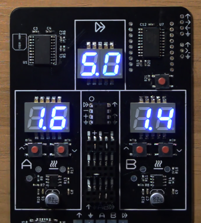
Main components on the Amper
Amper bill of materials (BOM)
54 components, 28 distinct parts.
| Qty | Part | Footprint | Refs |
|---|---|---|---|
| 1 | TM1637 | TM1637 | U1 |
| 3 | HDSM-441B | SLS0392FB4A1GD | U2, U3, U4 |
| 1 | 114-87-308-41-134161 (MCP602-E/P) | 114-87-308-41-134161-generated | U5 |
| 1 | ATtiny1606-S | SOIC-20W_7.5x12.8mm_P1.27mm | U7 |
| 2 | FDS9435A | SOIC-8_3.9x4.9mm_P1.27mm | Q1, Q2 |
| 1 | Conn_02x05_Odd_Even | 2.54_2x5_alternate-source-side | J1 |
| 1 | Conn_02x05_Odd_Even | 2.54_2x5_alternate | J2 |
| 1 | Conn_02x05_Odd_Even | 2.54_2x5_alternate-opamp-side | J3 |
| 1 | USB_C_Receptacle_USB2.0 | MC-303S | J4 |
| 1 | Conn_01x03 | PROG | J5 |
| 1 | Conn_01x04 | UART | J6 |
| 1 | Conn_01x05 | SolderHeader | J7 |
| 2 | Conn_01x09 | PinSocket_1x09_P2.54mm_Vertical_no_silk | J8, J9 |
| 2 | SW_Push | UpSwitch | SW1, SW3 |
| 2 | SW_Push | DnSwitch | SW2, SW4 |
| 1 | G*** | LargeOutput | svg2mod |
| 2 | 100pF | C_0603_1608Metric_Pad1.05x0.95mm_HandSolder | C1, C2 |
| 1 | 100nF | C_0603_1608Metric_Pad1.05x0.95mm_HandSolder | C3 |
| 1 | 2uF | C_0603_1608Metric_Pad1.05x0.95mm_HandSolder | C4 |
| 3 | 10uF | VT1H100M-CRD54 | C5, C10, C11 |
Show 8 more
| Qty | Part | Footprint | Refs |
|---|---|---|---|
| 4 | 1u | C_0603_1608Metric_Pad1.05x0.95mm_HandSolder | C6, C7, C8, C9 |
| 1 | 100n | C_0603_1608Metric_Pad1.05x0.95mm_HandSolder | C12 |
| 8 | 10K | R_0603_1608Metric_Pad1.05x0.95mm_HandSolder | R1, R2, R3, R4, R5, R6, R19, R20 |
| 2 | 15k | R_0603_1608Metric_Pad1.05x0.95mm_HandSolder | R7, R8 |
| 2 | 12k | R_0603_1608Metric_Pad1.05x0.95mm_HandSolder | R9, R11 |
| 2 | 20k | R_0603_1608Metric_Pad1.05x0.95mm_HandSolder | R10, R12 |
| 4 | 500 | R_0603_1608Metric_Pad1.05x0.95mm_HandSolder | R13, R14, R17, R18 |
| 2 | 4.7K | R_0603_1608Metric_Pad1.05x0.95mm_HandSolder | R15, R16 |
Amper design files
The KiCad project lives in the Threadnaught/amper repository on GitHub; these links point at the commit this page was built from.
Amper: common questions
What microcontroller does the Amper use?
The Amper is built around the ATtiny1606-S, from the AVR/Arduino family.
How big is the Amper PCB?
The Amper measures 80 × 99 mm, has 2 copper layers and is 1.6 mm thick.
How many components are on the Amper?
54 components, from 28 distinct parts. The full bill of materials is listed on this page.
Where can I download the Amper design files?
From the Threadnaught/amper repository on GitHub, which has the KiCad layout; the links under Design files point to each one.
Can I use the Amper design in my own project?
Yes, under the terms of its GPL-3.0 license, which Threadnaught chose for the repository.
Can I test firmware for the Amper without the hardware?
Yes. HardLabs builds a simulation of the board from its netlist and BOM, so you can run and debug AVR/Arduino firmware against it before you order a PCB.
Similar boards
 AVR/Arduino
Magspoof
samyk
35 × 29 mm11 parts2LNo license4.2k AVR/Arduino
Redox keyboard
mattdibi
162.2 × 126.5 mm77 parts2LMIT2.0k AVR/Arduino
Labrador
espotek-org
36.8 × 34.7 mm75 parts2LNo license1.2k AVR/Arduino
ModuleV450
stuartpittaway
30 × 61.4 mm39 parts2LCC-BY-NC-4.01.1k AVR/Arduino
V4
30 × 50 mm38 parts2LCC-BY-NC-4.01.1k AVR/Arduino
Discipline
coseyfannitutti
304.9 × 122.8 mm170 parts2LCC-BY-NC-4.01.0k