
Klipper-Expander

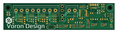
About the Klipper-Expander PCB
Klipper-Expander is an open source STM32 PCB design by timmit99, published on GitHub. It is a 2-layer board measuring 100 × 24 mm, with 55 components from 20 distinct parts.
Its main chip is the STM32F042F6PX, from the STM32 family. Other key parts include the AP2127K-3.3 and 74LVC1G17. By type, the board carries 22 resistors, 11 connectors, 7 diodes, 6 capacitors, 4 transistors and 3 ICs.
From the project
Simple MCU board for use with Klipper 3D Printer firmware with: - STM32F042F6P6 MCU with internal oscilator - SWD header for easy debugging - 4 3A Mosfet outputs - 2 Thermistor inputs - 1 Level Shifted Neopixel output - 1 GPIO header - I2C Header with Pullup Resistors
Simple MCU board for use with Klipper 3D Printer firmware with: - STM32F042F6P6 MCU with internal oscilator - SWD header for easy debugging - 4 3A Mosfet outputs - 2 Thermistor inputs - 1 Level Shifted Neopixel output - 1 GPIO header - I2C Header with Pullup Resistors
Parts that need to be sourced if assembled by JLC: - Micro USB port Molex 105017-0001 or equivalent Amazon - Keystone Fuse Holder Keystone 3544-2 - Mini Blade Fuse 2A 32V, 5A 32V, 10A 32V, or Amazon Assortment - 2 Pin Tactile Switch 6 x 3.5mm Button or Amazon - Screw Terminals 5.08mm Screw Terminals
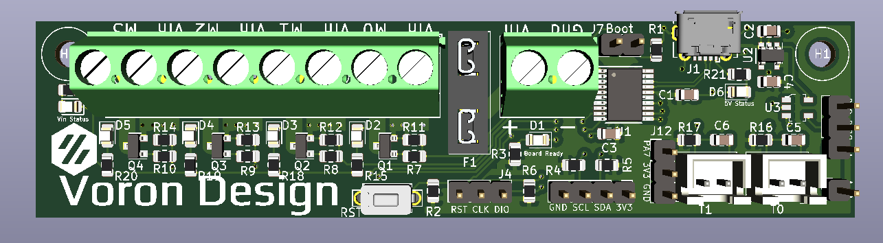
Main components on the Klipper-Expander
Klipper-Expander bill of materials (BOM)
55 components, 20 distinct parts — part numbers from the project's BOM.
| Qty | Part | Footprint | Refs |
|---|---|---|---|
| 1 | STM32F042F6PX STM32F042F6Px | TSSOP-20_4.4x6.5mm_P0.65mm | U1 |
| 1 | AP2127K-3.3 | SOT-23-5 | U2 |
| 1 | 74LVC1G17 | SOT-753 | U3 |
| 4 | IRLML6344TRPBF | SOT-23 | Q1, Q2, Q3, Q4 |
| 1 | USB_B_Micro | Molex-105017-0001-USBMicroB | J1 |
| 1 | CONN_01X04 Conn_01x04 | PinHeader_1x04_P2.54mm_Vertical | J2 |
| 3 | CONN_01X03 Conn_01x03 | PinHeader_1x03_P2.54mm_Vertical | J4, J11, J12 |
| 1 | Vin | 1x02_ScrewTerminal_Phoenix | J5 |
| 1 | SCREW_TERMINAL_01X08 Screw_Terminal_01x08 | 1x08_ScrewTerminal_Phoenix | J6 |
| 3 | CONN_01X02 Conn_01x02 | PinHeader_1x02_P2.54mm_Vertical | J7, J8, J9 |
| 1 | CONN_01X01 Conn_01x01 | PinHeader_1x01_P2.54mm_Vertical | J10 |
| 1 | Fuse | 3544-2_FuseHolder | F1 |
| 1 | SW_SPST | 2PinTactileButton | SW2 |
| 7 | LED | LED_0805_2012Metric | D1, D2, D3, D4, D5, D6, D7 |
| 2 | 0.1UF 0.1uF | C_0805_2012Metric | C1, C3 |
| 4 | 4.7UF 4.7uF | C_0805_2012Metric | C2, C4, C5, C6 |
| 7 | 10K | R_0805_2012Metric | R1, R2, R6, R11, R12, R13, R14 |
| 2 | 1K | R_0805_2012Metric | R3, R21 |
| 9 | 4.7K | R_0805_2012Metric | R4, R5, R15, R16, R17, R18, R19, R20 +1 |
| 4 | 100 | R_0805_2012Metric | R7, R8, R9, R10 |
Klipper-Expander design files
The KiCad project lives in the timmit99/Klipper-Expander repository on GitHub; these links point at the commit this page was built from.
Klipper-Expander: common questions
What microcontroller does the Klipper-Expander use?
The Klipper-Expander is built around the STM32F042F6PX, from the STM32 family.
How big is the Klipper-Expander PCB?
The Klipper-Expander measures 100 × 24 mm, has 2 copper layers and is 1.6 mm thick.
How many components are on the Klipper-Expander?
55 components, from 20 distinct parts, with part numbers taken from the project's own BOM. The full bill of materials is listed on this page.
Where can I download the Klipper-Expander design files?
From the timmit99/Klipper-Expander repository on GitHub, which has the KiCad layout and the BOM; the links under Design files point to each one.
Can I use the Klipper-Expander design in my own project?
The repository has no license, so all rights stay with timmit99. Use it as a reference, and ask the author before reusing the design.
Can I test firmware for the Klipper-Expander without the hardware?
Yes. HardLabs builds a simulation of the board from its netlist and BOM, so you can run and debug STM32 firmware against it before you order a PCB.
Similar boards
 STM32
LumenPnP Motherboard
opulo-inc
149 × 95 mm296 parts4LCC-BY-SA-4.03.7k STM32
Base
google
52.3 × 52.3 mm36 parts2LApache-2.02.9k STM32
Type g
169 × 30 mm24 parts2LApache-2.02.9k STM32
Main panel
234 × 84 mm26 parts4LApache-2.02.9k STM32
Type a
150 × 30 mm14 parts2LApache-2.02.9k STM32
Type c
188 × 30 mm17 parts2LApache-2.02.9k