
TORANEKO.Mk3

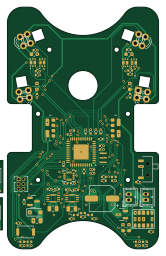
About the TORANEKO.Mk3 PCB
TORANEKO.Mk3 is an open source STM32 PCB design by Tokoro0917, published on GitHub under the MIT license. It is a 2-layer board measuring 40 × 64 mm, with 93 components from 34 distinct parts.
Its main chip is the STM32F411CEU6TR, from the STM32 family. Other key parts include the MP6551GQB-P, NCR321PASX, AS5047P-ATSM, LSM6DSRXTR and LXDC55FAAA-203. By type, the board carries 27 capacitors, 23 resistors, 17 diodes, 15 ICs, 6 connectors and 2 transistors.
From the project
ToraNeko.Mk3 のメイン基板(1枚基板・全機能統合、基板一体型シャーシ)のKiCadプロジェクトです。
ToraNeko.Mk3 のメイン基板(1枚基板・全機能統合、基板一体型シャーシ)のKiCadプロジェクトです。
KiCadプロジェクト本体(TORANEKO.Mk3.kicadpro / .kicadsch / .kicadpcb`)を作成済みです(現状は空、これから回路図を起こしていきます)。 このディレクトリには、実際に回路図を起こす前に固めておいた機能ブロック構成・ペリフェラル割り当て案・BOMドラフトも一緒に置いています。
正確なピン番号はKiCadで回路図を起こす際にデータシート(UFQFPN48パッケージ)で確定してください。 ここではどのペリフェラルをどのブロックに割り当てるかの方針のみ示します。
- SPIバス(IMU・エンコーダ用): LSM6DSRXTR、AS5047P × 2 は共通SPIバス上にCS(チップセレクト)を分けて接続する案。SPIバスを分割するかは配線の都合で判断。 - PWM(モータ駆動用): MP6551 × 2 に対し、1モータあたり2本(IN1/IN2、もしくはPWM+DIR)を想定。TIM1などの高機能タイマーを優先的に割り当てる。 - ADC(壁センサ用): LTR-209(受光)× 4組ぶんでADC 4チャンネル(PA3〜PA6)を使用。OSI5FU3A11C(発光)側は NCR321PAS(LED 1個につき1個)の…
Main components on the TORANEKO.Mk3
TORANEKO.Mk3 bill of materials (BOM)
93 components, 34 distinct parts — part numbers from the project's BOM.
| Qty | Part | Footprint | Refs |
|---|---|---|---|
| 2 | MP6551GQB-P | MP6551GQBP | IC1, IC2 |
| 4 | NCR321PASX | NCR321PASX | IC3, IC4, IC8, IC9 |
| 2 | AS5047P-ATSM | SOP65P640X120-14N | IC5, IC7 |
| 1 | STM32F411CEU6TR | QFN50P700X700X60-49N-D | IC6 |
| 1 | LSM6DSRXTR | LGA-14L_STM | U1 |
| 1 | LXDC55FAAA-203 | LXDC55FAAA203 | U2 |
| 2 | Encord | TN_ENC_Edge | U3, U5 |
| 2 | Encord_B | TN_ENC_Base | U4, U6 |
| 1 | IRLML6402 | SOT-23 | Q1 |
| 1 | IRLML6344 | SOT-23 | Q5 |
| 1 | CSTNE10M0G52Z000R0 | CSTNE10M0G52Z000R0 | Y1 |
| 2 | Conn_01x02_Pin | JST_ZH_B2B-ZR_1x02_P1.50mm_Vertical | J1, J4 |
| 2 | Conn_01x02_Pin | C_0805_2012Metric | J2, J5 |
| 1 | Conn_01x02_Male | C_0805_2012Metric | J3 |
| 1 | Conn_02x03_Odd_Even | PinHeader_2x03_P1.27mm_Vertical | J6 |
| 1 | SSSS810701 | SSSS810701 | S1 |
| 1 | SW_Push | SW_Push_SPST_NO_Alps_SKRK | SW1 |
| 8 | LED | LED_0402_1005Metric | D1, D18, D19, D20, D21, D22, D23, D24 |
| 4 | LED | LED_D3.0mm | D7, D8, D9, D10 |
| 1 | D | D_SOD-123F | D11 |
Show 14 more
| Qty | Part | Footprint | Refs |
|---|---|---|---|
| 4 | D_Photo_Filled | LED_D3.0mm | D13, D14, D15, D16 |
| 1 | 100u | CP_Elec_6.3x5.4 | C2 |
| 2 | 10 | C_0402_1005Metric | C3, C6 |
| 2 | 0.1 | C_0402_1005Metric | C4, C7 |
| 6 | 47u | C_0603_1608Metric | C9, C10, C11, C12, C13, C14 |
| 14 | 0.1u | C_0402_1005Metric | C15, C16, C18, C19, C21, C22, C23, C24 +6 |
| 2 | 10u | C_0402_1005Metric | C17, C20 |
| 5 | 10k | R_0402_1005Metric | R2, R4, R8, R9, R22 |
| 1 | 100K | R_0402_1005Metric | R5 |
| 1 | 47K | R_0402_1005Metric | R6 |
| 1 | 1.3K | R_0402_1005Metric | R7 |
| 4 | 5.1 | R_0402_1005Metric | R10, R11, R12, R13 |
| 7 | 2k | R_0402_1005Metric | R19, R20, R21, R27, R28, R29, R30 |
| 4 | 1k | R_0402_1005Metric | R23, R24, R25, R26 |
TORANEKO.Mk3 design files
The KiCad project lives in the Tokoro0917/ToraNeko.Mk3 repository on GitHub; these links point at the commit this page was built from.
TORANEKO.Mk3: common questions
What microcontroller does the TORANEKO.Mk3 use?
The TORANEKO.Mk3 is built around the STM32F411CEU6TR, from the STM32 family.
How big is the TORANEKO.Mk3 PCB?
The TORANEKO.Mk3 measures 40 × 64 mm, has 2 copper layers and is 0.6 mm thick.
How many components are on the TORANEKO.Mk3?
93 components, from 34 distinct parts, with part numbers taken from the project's own BOM. The full bill of materials is listed on this page.
Where can I download the TORANEKO.Mk3 design files?
From the Tokoro0917/ToraNeko.Mk3 repository on GitHub, which has the KiCad layout, the schematic and the BOM; the links under Design files point to each one.
Can I use the TORANEKO.Mk3 design in my own project?
Yes, under the terms of its MIT license, which Tokoro0917 chose for the repository.
Can I test firmware for the TORANEKO.Mk3 without the hardware?
Yes. HardLabs builds a simulation of the board from its netlist and BOM, so you can run and debug STM32 firmware against it before you order a PCB.
More boards in ToraNeko.Mk3
Similar boards
 STM32
LumenPnP Motherboard
opulo-inc
149 × 95 mm296 parts4LCC-BY-SA-4.03.7k STM32
Type g
google
169 × 30 mm24 parts2LApache-2.02.9k STM32
Main panel
234 × 84 mm26 parts4LApache-2.02.9k STM32
Base
52.3 × 52.3 mm36 parts2LApache-2.02.9k STM32
Type a
150 × 30 mm14 parts2LApache-2.02.9k STM32
Type c
188 × 30 mm17 parts2LApache-2.02.9k