
CAN-NODE-BOARD

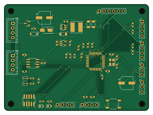
About the CAN-NODE-BOARD
CAN-NODE-BOARD is an open source STM32 PCB design by twenty-seven27, published on GitHub. It is a 4-layer board measuring 76 × 56 mm, with 58 components from 37 distinct parts.
Its main chip is the STM32G431KBT6, from the STM32 family. Other key parts include the AP63205WU-7, AP2112K-3.3TRG1 and TCAN1042VDRQ1. By type, the board carries 20 capacitors, 15 resistors, 10 connectors, 4 ICs, 4 diodes and 2 inductors.
It belongs with the robotics & motion and power & battery designs in this gallery.
From the project
PCB Project
One custom PCB that replaces the Arduino Mega + CAN Bus Shield stack on every node of a 4WD autonomous parking robot. The robot's three nodes (sensor, receive, motor) talk over CAN; each one now runs the same board and the same firmware image, and a single resistor tells the board which node it is.
PB0 (an ADC input) sits in the middle of a divider: a fixed 10 kΩ pull-up (R4) and a role resistor R5 to ground. At boot the firmware averages eight ADC samples, picks the nearest bin, and from that sets its CAN IDs, acceptance filters and which peripherals it starts.
Main components on the CAN-NODE-BOARD
CAN-NODE-BOARD bill of materials (BOM)
58 components, 37 distinct parts.
| Qty | Part | Footprint | Refs |
|---|---|---|---|
| 1 | AP63205WU-7 AP63205WU | TSOT-23-6 | U1 |
| 1 | AP2112K-3.3TRG1 AP2112K-3.3 | SOT-23-5 | U2 |
| 1 | STM32G431KBT6 | LQFP-32_7x7mm_P0.8mm | U3 |
| 1 | TCAN1042VDRQ1 | SOIC-8_3.9x4.9mm_P1.27mm | U4 |
| 1 | AO3407A | SOT-23 | Q1 |
| 1 | 8 MHz 3225 crystal, CL = 10 pF, +/-20 ppm 8MHz | Crystal_SMD_3225-4Pin_3.2x2.5mm | Y1 |
| 2 | JST B4B-XH-A BUS | JST_XH_B4B-XH-A_1x04_P2.50mm_Vertical | J1, J2 |
| 1 | 1x3 2.54 mm header SERVO | PinHeader_1x03_P2.54mm_Vertical | J3 |
| 1 | 1x4 2.54 mm header ULTRASONIC | PinHeader_1x04_P2.54mm_Vertical | J4 |
| 1 | 1x4 2.54 mm header ENC_L | PinHeader_1x04_P2.54mm_Vertical | J5 |
| 1 | 1x4 2.54 mm header ENC_R | PinHeader_1x04_P2.54mm_Vertical | J6 |
| 1 | 1x6 2.54 mm header MOTOR | PinHeader_1x06_P2.54mm_Vertical | J7 |
| 1 | 1x3 2.54 mm header UART | PinHeader_1x03_P2.54mm_Vertical | J8 |
| 1 | 1x4 2.54 mm header AUX | PinHeader_1x04_P2.54mm_Vertical | J9 |
| 1 | 2x5 1.27 mm SMD header (Cortex debug) SWD | PinHeader_2x05_P1.27mm_Vertical_SMD | J10 |
| 1 | E-Switch TL3342F160QG RESET | SW_SPST_TL3342 | SW1 |
| 1 | BZT52C12-7-F BZT52C12 | D_SOD-123 | D1 |
| 1 | SMAJ18CA | D_SMA | D2 |
| 1 | Green LED 0603 GREEN | LED_0603_1608Metric | D3 |
| 1 | Blue LED 0603 BLUE | LED_0603_1608Metric | D4 |
Show 17 more
| Qty | Part | Footprint | Refs |
|---|---|---|---|
| 1 | Murata BLM18AG601SN1D (600 R at 100 MHz) 600R | L_0603_1608Metric | FB1 |
| 1 | Bourns SRN6045TA-4R7M 4.7u | L_Bourns_SRN6045TA | L1 |
| 1 | Aluminium electrolytic 47 uF 35 V 6.3x7.7 47u | CP_Elec_6.3x7.7 | C1 |
| 1 | X5R 10 uF 35 V 1206 10u | C_1206_3216Metric | C2 |
| 8 | X7R 100 nF 50 V 0603 100n | C_0603_1608Metric | C3, C8, C9, C12, C13, C16, C18, C19 |
| 2 | X5R 22 uF 16 V 1206 22u | C_1206_3216Metric | C4, C5 |
| 3 | X7R 1 uF 16 V 0603 1u | C_0603_1608Metric | C6, C7, C11 |
| 1 | X5R 4.7 uF 10 V 0603 4.7u | C_0603_1608Metric | C10 |
| 2 | C0G 15 pF 50 V 0603 15p | C_0603_1608Metric | C14, C15 |
| 1 | Aluminium electrolytic 220 uF 10 V 6.3x7.7 220u | CP_Elec_6.3x7.7 | C17 |
| 1 | C0G 4.7 nF 50 V 0603 4.7n | C_0603_1608Metric | C20 |
| 7 | 10k | R_0603_1608Metric | R1, R3, R7, R10, R11, R12, R13 |
| 3 | 1k | R_0603_1608Metric | R2, R6, R8 |
| 1 | 10k 1% 0603 10k | R_0603_1608Metric | R4 |
| 1 | per role table R_ROLE | R_0603_1608Metric | R5 |
| 1 | 2k | R_0603_1608Metric | R9 |
| 2 | 60.4 ohm 1% 0603 60.4 | R_0603_1608Metric | R14, R15 |
CAN-NODE-BOARD design files
The KiCad project lives in the twenty-seven27/CAN-NODE-BOARD repository on GitHub; these links point at the commit this page was built from.
- Layoutcan-node.kicad_pcb
- Schematiccan-node.kicad_sch
CAN-NODE-BOARD: common questions
What microcontroller does the CAN-NODE-BOARD use?
The CAN-NODE-BOARD is built around the STM32G431KBT6, from the STM32 family.
How big is the CAN-NODE-BOARD?
The CAN-NODE-BOARD measures 76 × 56 mm, has 4 copper layers and is 1.6 mm thick.
How many components are on the CAN-NODE-BOARD?
58 components, from 37 distinct parts. The full bill of materials is listed on this page.
Where can I download the CAN-NODE-BOARD design files?
From the twenty-seven27/CAN-NODE-BOARD repository on GitHub, which has the KiCad layout and the schematic; the links under Design files point to each one.
Can I use the CAN-NODE-BOARD design in my own project?
The repository has no license, so all rights stay with twenty-seven27. Use it as a reference, and ask the author before reusing the design.
Can I test firmware for the CAN-NODE-BOARD without the hardware?
Yes. HardLabs builds a simulation of the board from its netlist and BOM, so you can run and debug STM32 firmware against it before you order a PCB.
Similar boards
 STM32
LumenPnP Motherboard
opulo-inc
149 × 95 mm296 parts4LCC-BY-SA-4.03.7k STM32
Type g
google
169 × 30 mm24 parts2LApache-2.02.9k STM32
Base
52.3 × 52.3 mm36 parts2LApache-2.02.9k STM32
Main panel
234 × 84 mm26 parts4LApache-2.02.9k STM32
Type a
150 × 30 mm14 parts2LApache-2.02.9k STM32
Type c
188 × 30 mm17 parts2LApache-2.02.9k