
Breakbeamreceiver


About the Breakbeamreceiver PCB
Breakbeamreceiver is an open source PCB design by UBC-Thunderbots, published on GitHub. It is a board measuring 20.3 × 17.8 mm, with 4 components from 4 distinct parts.
By type, the board carries 1 transistor, 1 relay and 1 resistor.
It belongs with the robotics & motion and rf & radio designs in this gallery.
From the project
All things electrical, from radio communication to BLDC motors. Zappity zap!
Our repository for all things electrical! To get started, please see the getting started document.
If you are already set up, go to the electrical system overview.
Breakbeamreceiver bill of materials (BOM)
4 components, 4 distinct parts.
| Qty | Part | Footprint | Refs |
|---|---|---|---|
| 1 | TEMT1000 | PHOTOTRANS-TEMT1000 | Q1 |
| 1 | P*** | 2-56hole | 2-56hole |
| 1 | CONN_01X03 | connector_0_49_in_3pin | K1 |
| 1 | 100R | R_0805_HandSoldering | R1 |
Breakbeamreceiver design files
The KiCad project lives in the UBC-Thunderbots/Electrical repository on GitHub; these links point at the commit this page was built from.
Breakbeamreceiver: common questions
How big is the Breakbeamreceiver PCB?
The Breakbeamreceiver measures 20.3 × 17.8 mm and is 1.6002 mm thick.
How many components are on the Breakbeamreceiver?
4 components, from 4 distinct parts. The full bill of materials is listed on this page.
Where can I download the Breakbeamreceiver design files?
From the UBC-Thunderbots/Electrical repository on GitHub, which has the KiCad layout; the links under Design files point to each one.
Can I use the Breakbeamreceiver design in my own project?
The repository has no license, so all rights stay with UBC-Thunderbots. Use it as a reference, and ask the author before reusing the design.
More boards in Electrical
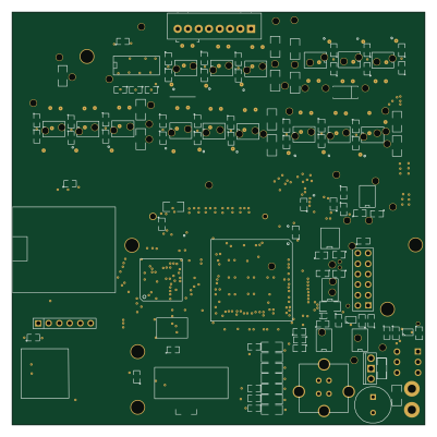 STM32
Main
100 × 100 mm186 partsNo license3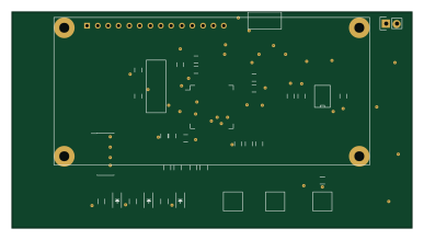 STM32
Breakbeam processor
96.5 × 52.1 mm46 partsNo license3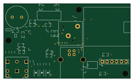 STM32
Dongle
67.3 × 40 mm39 partsNo license3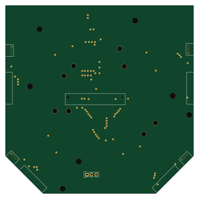
Breakout
100 × 100 mm37 partsNo license3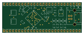 STM32
Workshop board
66.7 × 25.8 mm35 partsNo license3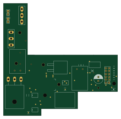
Chicker
100 × 98 mm35 partsNo license3
Breakbeam
20.3 × 16.5 mm4 partsNo license3
Similar boards
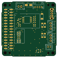
Stack chan
stack-chan
50 × 50 mm33 parts2LApache-2.01.7k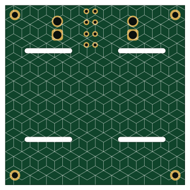
Cube batteryboard
willem-pennings
95 × 95 mm4 parts2LGPL-3.01.1k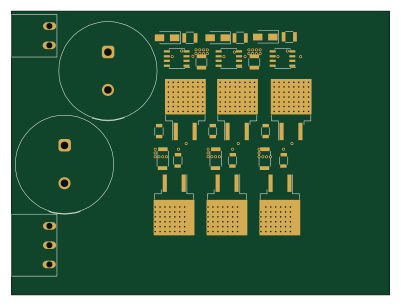
Trollerv2
rene-dev
100 × 75 mm33 parts4LGPL-3.0979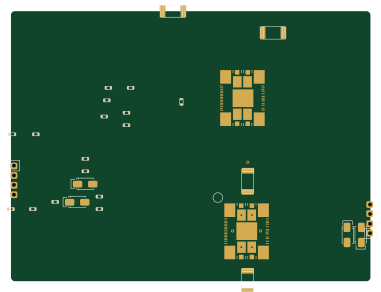
Powerstep
95.2 × 71.5 mm28 parts4LGPL-3.0979
11ua
57.3 × 19 mm26 parts2LGPL-3.0979
Diff driver
32 × 22 mm14 parts2LGPL-3.0979