
Usbc rtl sdr


About the Usbc rtl sdr PCB
Usbc rtl sdr is an open source PCB design by umbertoragone, published on GitHub under the MIT license. It is a 2-layer board measuring 10 × 12 mm, with 3 components from 2 distinct parts.
By type, the board carries 2 resistors and 1 connector.
It belongs with the rf & radio designs in this gallery.
From the project
A PCB adapter board to convert your RTL-SDR V3/V4 dongle from USB-A to USB-C
Included in this repository is the HTML BOM (ibom.html) to help you in the assembly/soldering process after you received your PCBs. You can access the Interactive HTML BOM here, without having to download the .html file. Also, here is the list of components you will have to source and solder yourself:
Usbc rtl sdr bill of materials (BOM)
3 components, 2 distinct parts — part numbers from the project's BOM.
| Qty | Part | Footprint | Refs |
|---|---|---|---|
| 1 | USB_C_RECEPTACLE_USB2.0 USB_C_Receptacle_USB2.0 | TYPE-C-31-M-12 | J1 |
| 2 | 5K1 5k1 | R_0402_1005Metric | R1, R2 |
Usbc rtl sdr design files
The KiCad project lives in the umbertoragone/usbc-rtl-sdr repository on GitHub; these links point at the commit this page was built from.
Usbc rtl sdr: common questions
How big is the Usbc rtl sdr PCB?
The Usbc rtl sdr measures 10 × 12 mm, has 2 copper layers and is 1.2 mm thick.
How many components are on the Usbc rtl sdr?
3 components, from 2 distinct parts, with part numbers taken from the project's own BOM. The full bill of materials is listed on this page.
Where can I download the Usbc rtl sdr design files?
From the umbertoragone/usbc-rtl-sdr repository on GitHub, which has the KiCad layout, the schematic and the BOM; the links under Design files point to each one.
Can I use the Usbc rtl sdr design in my own project?
Yes, under the terms of its MIT license, which umbertoragone chose for the repository.
Similar boards

Radioberry preamp
pa3gsb
65 × 56 mm137 parts2LNo license675
Radioberry juice
65 × 56 mm87 parts2LNo license675
Hat
65 × 56 mm81 parts2LNo license675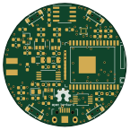
Open smartwatch light
Open-Smartwatch
36.1 × 36.1 mm51 parts4LGPL-3.0246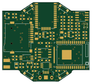
Open smartwatch gps
45 × 41 mm67 parts4LGPL-3.0241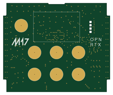
Module17 HMI
M17-Project
97 × 80.9 mm49 parts4LCERN-OHL-W-2.0129