
UG56-attiny13a pwm controller

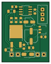
About the UG56-attiny13a pwm controller PCB
UG56-attiny13a pwm controller is an open source AVR/Arduino PCB design by universalgeek56, published on GitHub under the MIT license. It is a 2-layer board measuring 25 × 31.5 mm, with 21 components from 17 distinct parts.
Its main chip is the ATtiny13A-SS, from the AVR/Arduino family. Other key parts include the L78L05_SOT89. By type, the board carries 7 capacitors, 5 resistors, 4 test points, 2 ICs and 1 diode.
It belongs with the robotics & motion and sensors designs in this gallery.
From the project
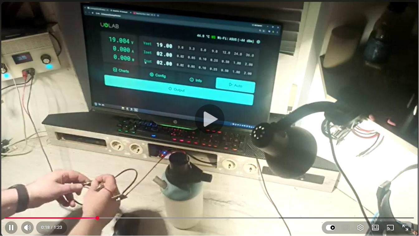
ATtiny13A-based PWM controller for brushed motors, lights, heaters and fans. Soft start. Soft stop. Voltage compensation. Protection. Hysteresis. Same hardware. Different loads. Scale it with better MOSFETs. Just a PWM core. What you connect to the ADC defines what it becomes.
It will spin a motor. It will dim a lamp.
- Soft start and soft stop (2.5 s up, 1.2 s down) - Voltage compensation (run a 12 V motor from a 19 V supply) - Overvoltage and undervoltage protection (9–25 V) - Potentiometer hysteresis (no chattering near zero) - Complete MOSFET shutdown (no leakage when OFF) - Minimum PWM threshold for reliable motor startup
- Brushed DC motors (fans, pumps, drills, cyclones) - High-power LEDs and halogen lamps as a dimmer - DC heating elements (soldering irons, hot-wire cutters, heaters)
Main components on the UG56-attiny13a pwm controller
UG56-attiny13a pwm controller bill of materials (BOM)
21 components, 17 distinct parts.
| Qty | Part | Footprint | Refs |
|---|---|---|---|
| 1 | ATtiny13A-SS | SOIC-8_3.9x4.9mm_P1.27mm | U1 |
| 1 | L78L05_SOT89 | SOT-89-3 | U2 |
| 1 | 10K | Potentiometer_Bourns_3296W_Vertical | RV1 |
| 1 | VCC | TestPoint_THTPad_2.0x2.0mm_Drill1.0mm | TP1 |
| 1 | Motor+ | TestPoint_THTPad_2.0x2.0mm_Drill1.0mm | TP2 |
| 1 | Motor- | TestPoint_THTPad_2.0x2.0mm_Drill1.0mm | TP3 |
| 1 | GND | TestPoint_THTPad_2.0x2.0mm_Drill1.0mm | TP4 |
| 1 | IRLR2905PBF | TO-252 | V1 |
| 1 | SS34 | D_SMA | D2 |
| 1 | 100uF | CP_Elec_6.3x7.7 | C1 |
| 5 | 0.1uF | C_0805_2012Metric_Pad1.18x1.45mm_HandSolder | C2, C4, C5, C7, C8 |
| 1 | 100uF | CP_Elec_4x4.5 | C3 |
| 1 | 00 | R_1206_3216Metric_Pad1.30x1.75mm_HandSolder | R1 |
| 1 | 100R | R_0805_2012Metric_Pad1.20x1.40mm_HandSolder | R3 |
| 1 | 100K | R_1206_3216Metric_Pad1.30x1.75mm_HandSolder | R4 |
| 1 | 10K(4.7K for 24V motor) | R_0805_2012Metric_Pad1.20x1.40mm_HandSolder | R5*1 |
| 1 | 100K | R_0805_2012Metric_Pad1.20x1.40mm_HandSolder | R6 |
UG56-attiny13a pwm controller design files
The KiCad project lives in the universalgeek56/UG56-attiny13a-pwm-controller repository on GitHub; these links point at the commit this page was built from.
UG56-attiny13a pwm controller: common questions
What microcontroller does the UG56-attiny13a pwm controller use?
The UG56-attiny13a pwm controller is built around the ATtiny13A-SS, from the AVR/Arduino family.
How big is the UG56-attiny13a pwm controller PCB?
The UG56-attiny13a pwm controller measures 25 × 31.5 mm, has 2 copper layers and is 1.6 mm thick.
How many components are on the UG56-attiny13a pwm controller?
21 components, from 17 distinct parts. The full bill of materials is listed on this page.
Where can I download the UG56-attiny13a pwm controller design files?
From the universalgeek56/UG56-attiny13a-pwm-controller repository on GitHub, which has the KiCad layout and the schematic; the links under Design files point to each one.
Can I use the UG56-attiny13a pwm controller design in my own project?
Yes, under the terms of its MIT license, which universalgeek56 chose for the repository.
Can I test firmware for the UG56-attiny13a pwm controller without the hardware?
Yes. HardLabs builds a simulation of the board from its netlist and BOM, so you can run and debug AVR/Arduino firmware against it before you order a PCB.
Similar boards
 AVR/Arduino
Redox keyboard
mattdibi
162.2 × 126.5 mm77 parts2LMIT2.0k AVR/Arduino
ModuleV450
stuartpittaway
30 × 61.4 mm39 parts2LCC-BY-NC-4.01.1k AVR/Arduino
V4
30 × 50 mm38 parts2LCC-BY-NC-4.01.1k AVR/Arduino
Discipline
coseyfannitutti
304.9 × 122.8 mm170 parts2LCC-BY-NC-4.01.0k AVR/Arduino
Megadesk
gcormier
41.7 × 32.2 mm23 parts2LGPL-3.0818 AVR/Arduino
Easyduino Atmega Nano
Hanqaqa
43.4 × 18 mm30 parts4LCERN-OHL-P-2.0746