
USTSIPM01

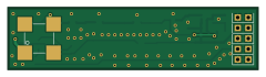
About the USTSIPM01 PCB
USTSIPM01 is an open source PCB design by ust-modules, published on GitHub. It is a 2-layer board measuring 60 × 15 mm, with 39 components from 20 distinct parts.
Other key parts include the MICROFC-60035-SMT-TR(1), OPA836IDB and MAX5026. By type, the board carries 16 capacitors, 12 resistors, 5 connectors, 3 ICs, 2 diodes and 1 inductor.
It belongs with the sensors and test & measurement designs in this gallery.
From the project
Silicon photomultiplier interface module
Complete analog front‑end for Silicon Photomultipliers (SiPM). The module provides resistor-configurable high‑voltage bias for the SiPM sensor and a low‑noise, wideband readout stage suitable for timing and amplitude measurements.
Footprint for onsemi MicroFC‑60035‑SMT SiPM (6×6 mm, 35 µm microcells). On‑board high‑voltage boost converter MAX5026 generating the SiPM bias from the +5 V rail. Precision feedback network with design equation Vout = 1.25 V × (1 + R2/R3); default configuration targets to 31.7 V bias. Low‑noise wideband amplifier stage OPA836 for SiPM signal readout. * Pin-header…
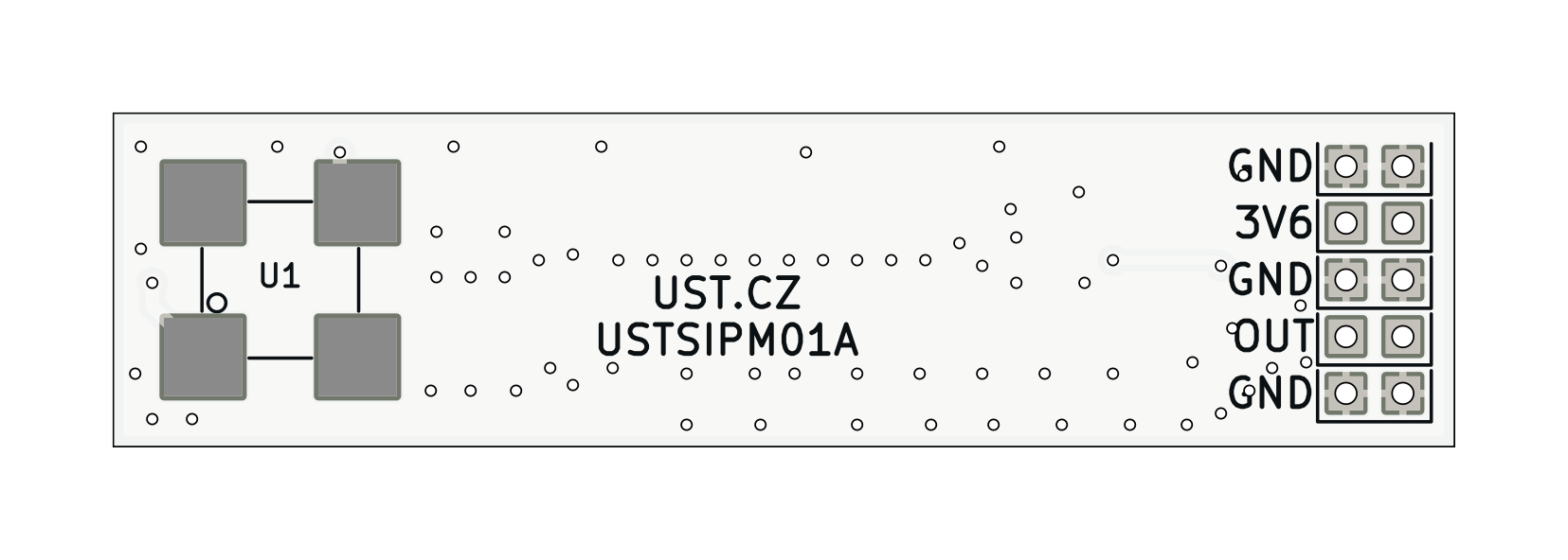
Main components on the USTSIPM01
USTSIPM01 bill of materials (BOM)
39 components, 20 distinct parts — part numbers from the project's BOM.
| Qty | Part | Footprint | Refs |
|---|---|---|---|
| 1 | MICROFC-60035-SMT-TR(1) | MicroFC−60035−SMT | U1 |
| 1 | OPA836IDB | SOT-23-6 | U2 |
| 1 | MAX5026 | SOT-23-6_Handsoldering | U3 |
| 5 | HEADER_2X01_PARALLEL HEADER_2x01_PARALLEL | Straight_2x01 | J4, J5, J6, J8, J9 |
| 1 | BZX585-B5V6.115 | D_SOD-523 | D1 |
| 1 | NSR05T40XV2T5G | D_SOD-523 | D2 |
| 1 | 400uH cca 0,9mA NLV10JT391 | L_1210_3225Metric_Pad1.42x2.65mm_HandSolder | L1 |
| 1 | 10UF/35V 10uF/35V | C_0805_2012Metric | C1 |
| 6 | 10UF 10uF | C_0805_2012Metric | C2, C3, C4, C7, C14, C15 |
| 6 | 100NF 100nF | C_0805_2012Metric | C5, C6, C8, C11, C12, C50 |
| 1 | 10NF 10nF | C_0805_2012Metric | C9 |
| 2 | 1UF/50V 1uF/50V | C_0805_2012Metric | C10, C13 |
| 3 | 100R | R_0805_2012Metric | R1, R3, R13 |
| 3 | 10R | R_0805_2012Metric | R2, R4, R5 |
| 1 | 3M9 | R_0805_2012Metric | R6 |
| 1 | 160K 160k | R_0805_2012Metric | R7 |
| 1 | 470R | R_0805_2012Metric | R9 |
| 1 | 12K 12k | R_0805_2012Metric | R10 |
| 1 | 10K 10k | R_0805_2012Metric | R11 |
| 1 | 1k | R_0805_2012Metric | R12 |
USTSIPM01 design files
The KiCad project lives in the ust-modules/USTSIPM01 repository on GitHub; these links point at the commit this page was built from.
USTSIPM01: common questions
How big is the USTSIPM01 PCB?
The USTSIPM01 measures 60 × 15 mm, has 2 copper layers and is 1.6 mm thick.
How many components are on the USTSIPM01?
39 components, from 20 distinct parts, with part numbers taken from the project's own BOM. The full bill of materials is listed on this page.
Where can I download the USTSIPM01 design files?
From the ust-modules/USTSIPM01 repository on GitHub, which has the KiCad layout, the schematic and the BOM; the links under Design files point to each one.
Can I use the USTSIPM01 design in my own project?
The repository has no license, so all rights stay with ust-modules. Use it as a reference, and ask the author before reusing the design.
Similar boards
LevelShifter
gusmanb
28.3 × 39.8 mm21 parts2LGPL-3.05.0k
StackLink
52.3 × 10.5 mm5 parts2LGPL-3.05.0k
AnalyzerBoxPCB fork
52.7 × 47.9 mm54 parts4LGPL-3.05.0k
Sensor smd
scottbez1
40 × 20 mm5 parts2LApache-2.04.2k
Sensors
StuckAtPrototype
15.2 × 9 mm14 parts4LApache-2.03.8k
Microphone
Mentra-Community
5.5 × 6.1 mm6 parts2LMIT1.2k