
V2

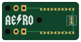
About the V2 PCB
V2 is an open source PCB design by uvmaero, published on GitHub under the CC-BY-SA-4.0 license. It is a 2-layer board measuring 40.6 × 20.3 mm, with 13 components from 3 distinct parts.
By type, the board carries 10 resistors, 2 connectors and 1 diode.
From the project
UVM AERO boards.
This repo was originally @willemcvu 's personal AERO boards repo. From 2019-20 onward it will be used by all of AERO to store boards designed for the AERO cars.
Some are finished and have been produced, tested, etc. Others have not. Up to you to figure out if a particular board might be useful for your needs.
If you do produce a board, let me know! I'd love to know what you're using it for.
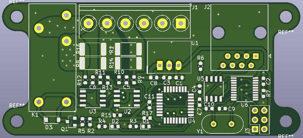
V2 bill of materials (BOM)
13 components, 3 distinct parts — part numbers from the project's BOM.
| Qty | Part | Footprint | Refs |
|---|---|---|---|
| 2 | Conn_01x02 | TE_MATE-N-LOK_1-770866-x_1x02_P4.14mm_Vertical | J1, J2 |
| 1 | RED_LED | LPA-C011301S-x LED 0805 LIGHT PIPE SINGLE VERT SMD | D1 |
| 10 | 1k | R_0805_2012Metric | R1, R2, R3, R4, R5, R6, R7, R8 +2 |
V2 design files
The KiCad project lives in the uvmaero/AERO-Boards-KiCad repository on GitHub; these links point at the commit this page was built from.
V2: common questions
How big is the V2 PCB?
The V2 measures 40.6 × 20.3 mm, has 2 copper layers and is 1.6 mm thick.
How many components are on the V2?
13 components, from 3 distinct parts, with part numbers taken from the project's own BOM. The full bill of materials is listed on this page.
Where can I download the V2 design files?
From the uvmaero/AERO-Boards-KiCad repository on GitHub, which has the KiCad layout and the BOM; the links under Design files point to each one.
Can I use the V2 design in my own project?
Yes, under the terms of its CC-BY-SA-4.0 license, which uvmaero chose for the repository.
More boards in AERO-Boards-KiCad
 AVR/Arduino
Interface board
157.5 × 109.2 mm70 parts2LCC-BY-SA-4.03 AVR/Arduino
DC DCBoard
185.4 × 68.6 mm65 parts2LCC-BY-SA-4.03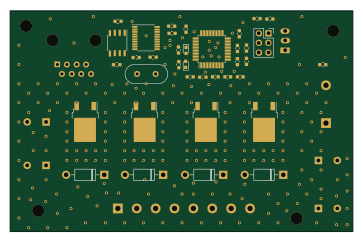 AVR/Arduino
FanBoy
90.7 × 58.4 mm45 parts2LCC-BY-SA-4.03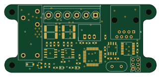 AVR/Arduino
GLVColoumbCounterTest
80.9 × 36.2 mm43 parts2LCC-BY-SA-4.03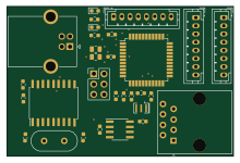 AVR/Arduino
Can game controller
55 × 36.5 mm30 parts2LCC-BY-SA-4.03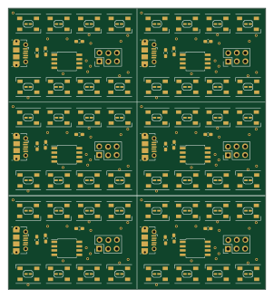 AVR/Arduino
Demo board panelized
75 × 82.1 mm14 parts2LCC-BY-SA-4.03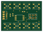 AVR/Arduino
Demo board
37.5 × 27.3 mm14 parts2LCC-BY-SA-4.03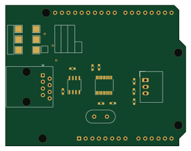
CANShield
69.1 × 53.9 mm14 parts2LCC-BY-SA-4.03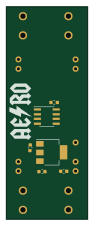 AVR/Arduino
TSAL-driver
21.6 × 56.5 mm11 parts2LCC-BY-SA-4.03