
Quad Motor Driver

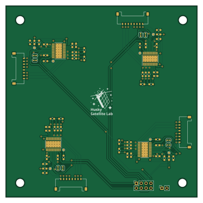
About the Quad Motor Driver PCB
Quad Motor Driver is an open source PCB design by UWCubeSat, published on GitHub. It is a 2-layer board measuring 100 × 100 mm, with 70 components from 13 distinct parts.
Other key parts include the DRV10970. By type, the board carries 32 resistors, 20 capacitors, 8 jumpers, 6 connectors and 4 ICs.
It belongs with the robotics & motion designs in this gallery.
From the project
PCB Design Files for 1U RW Test Stand
The Quad Motor Driver board contains four DRV10970 BLDC motor driver ICs and is intended for driving the Faulhaber 1509 motors that spin HuskySat-2's reaction wheels. The motors are connected with eight-pin Molex Pico-Lock connectors.
The board contains two headers. The first contains labeled pins for ground and a 5V power input. The second contains PWM and direction control (FR) pins for each of the four motors. Each of the four motor driver subsystems has two solder jumpers. The lower-numbered jumper may be soldered closed to enable motor braking when the PWM signal is zero. If left…
Main components on the Quad Motor Driver
Quad Motor Driver bill of materials (BOM)
70 components, 13 distinct parts.
| Qty | Part | Footprint | Refs |
|---|---|---|---|
| 4 | DRV10970 | HTSSOP-24-1EP_4.4x7.8mm_P0.65mm_EP3.4x7.8mm_Mask2.4x4.68mm_ThermalVias | U1, U2, U3, U4 |
| 1 | Conn_01x02_Female | PinSocket_1x02_P2.54mm_Vertical | J1 |
| 1 | Conn_02x04_Odd_Even | PinSocket_2x04_P2.54mm_Vertical | J2 |
| 4 | Conn_01x08_MountingPin | Molex_Pico-Lock_504050-0891_1x08-1MP_P1.50mm_Horizontal | J3, J4, J5, J6 |
| 8 | Jumper | SolderJumper-2_P1.3mm_Open_RoundedPad1.0x1.5mm | JP1, JP2, JP3, JP4, JP5, JP6, JP7, JP8 |
| 4 | 0.1uF X7R | C_0603_1608Metric_Pad1.08x0.95mm_HandSolder | C1, C6, C11, C16 |
| 4 | 1uF 16V | C_0603_1608Metric_Pad1.08x0.95mm_HandSolder | C2, C7, C12, C17 |
| 4 | 10uF 25V | C_0603_1608Metric_Pad1.08x0.95mm_HandSolder | C3, C8, C13, C18 |
| 4 | 2.2uF 10V | C_0603_1608Metric_Pad1.08x0.95mm_HandSolder | C4, C9, C14, C19 |
| 4 | 1uF | C_0603_1608Metric_Pad1.08x0.95mm_HandSolder | C5, C10, C15, C20 |
| 20 | 3.3k | R_0603_1608Metric_Pad0.98x0.95mm_HandSolder | R1, R2, R4, R5, R6, R9, R10, R12 +12 |
| 8 | 10k | R_0603_1608Metric_Pad0.98x0.95mm_HandSolder | R3, R8, R11, R16, R19, R24, R27, R32 |
| 4 | 24k | R_0603_1608Metric_Pad0.98x0.95mm_HandSolder | R7, R15, R23, R31 |
Quad Motor Driver design files
The KiCad project lives in the UWCubeSat/1U_RW_Hardware repository on GitHub; these links point at the commit this page was built from.
Quad Motor Driver: common questions
How big is the Quad Motor Driver PCB?
The Quad Motor Driver measures 100 × 100 mm, has 2 copper layers and is 1.6 mm thick.
How many components are on the Quad Motor Driver?
70 components, from 13 distinct parts. The full bill of materials is listed on this page.
Where can I download the Quad Motor Driver design files?
From the UWCubeSat/1U_RW_Hardware repository on GitHub, which has the KiCad layout and the schematic; the links under Design files point to each one.
Can I use the Quad Motor Driver design in my own project?
The repository has no license, so all rights stay with UWCubeSat. Use it as a reference, and ask the author before reusing the design.
More boards in 1U_RW_Hardware
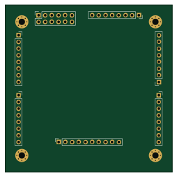
Similar boards

Stack chan
stack-chan
50 × 50 mm33 parts2LApache-2.01.7k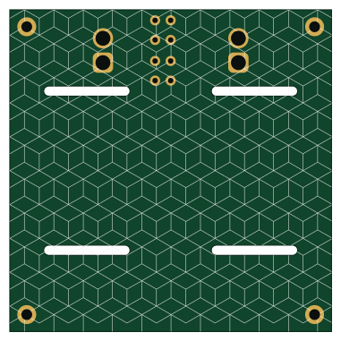
Cube batteryboard
willem-pennings
95 × 95 mm4 parts2LGPL-3.01.1k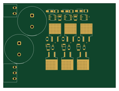
Trollerv2
rene-dev
100 × 75 mm33 parts4LGPL-3.0979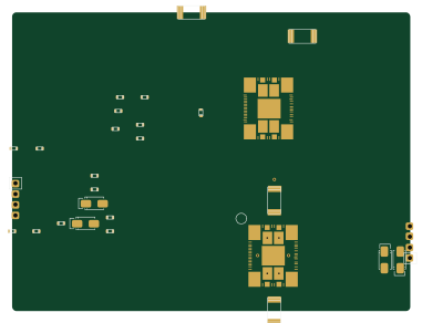
Powerstep
95.2 × 71.5 mm28 parts4LGPL-3.0979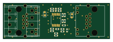
11ua
57.3 × 19 mm26 parts2LGPL-3.0979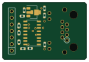
Diff driver
32 × 22 mm14 parts2LGPL-3.0979