
Load bank fan controller

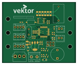
About the Load bank fan controller PCB
Load bank fan controller is an open source AVR/Arduino PCB design by vektordaya-mekatrika, published on GitHub. It is a 2-layer board measuring 66.3 × 54.8 mm, with 48 components from 30 distinct parts.
Its main chip is the ATmega328P-A, from the AVR/Arduino family. Other key parts include the AMS1117-5.0 and LM2904DT. By type, the board carries 16 resistors, 10 capacitors, 8 connectors, 3 ICs, 3 diodes and 2 transistors.
Main components on the Load bank fan controller
Load bank fan controller bill of materials (BOM)
48 components, 30 distinct parts — part numbers from the project's BOM.
| Qty | Part | Footprint | Refs |
|---|---|---|---|
| 1 | ATmega328P-A Microchip Tech | TQFP-32_7x7mm_P0.8mm | U1 |
| 1 | AMS1117-5.0 Advanced Monolithic Systems | SOT-223-3_TabPin2 | U2 |
| 1 | LM2904DT LM2904 STMicroelectronics | SO-8_3.9x4.9mm_P1.27mm | U3 |
| 2 | IRLML0030TRPBF IRLML0030 Infineon Technologies | SOT-23 | Q1, Q2 |
| 1 | X49SD16MSD2SC Crystal YXC Crystal Oscillators | Crystal_HC49-U_Vertical | Y1 |
| 1 | XD-2510-4A FAN1 chxunda | Molex_KK-254_AE-6410-04A_1x04_P2.54mm_Vertical | J1 |
| 1 | ZX-XH2.54-2PZZ TEMP1 Megastar | JST_XH_B2B-XH-A_1x02_P2.50mm_Vertical | J2 |
| 1 | WJ500V-5.08-2P RELAY Ningbo Kangnex Elec | TerminalBlock_RND_205-00232_1x02_P5.08mm_Horizontal | J3 |
| 1 | ZX-XH2.54-2PZZ TEMP2 Megastar | JST_XH_B2B-XH-A_1x02_P2.50mm_Vertical | J4 |
| 1 | XD-2510-4A FAN2 chxunda | Molex_KK-254_AE-6410-04A_1x04_P2.54mm_Vertical | J5 |
| 1 | ZX-PZ2.54-2-3PZZ ISP Megastar | PinHeader_2x03_P2.54mm_Vertical | J6 |
| 1 | XD-2510-4A FAN3 chxunda | Molex_KK-254_AE-6410-04A_1x04_P2.54mm_Vertical | J7 |
| 1 | HX VH3.96-3P ZZ 12V IN hanxia | JST_VH_B3P-VH-B_1x03_P3.96mm_Vertical | J8 |
| 1 | TMB12A12 Buzzer Jiangsu Huaneng Elec | Buzzer_12x9.5RM7.6 | BZ1 |
| 2 | 1201578 Phoenix Contact | DINRailAdapter_3xM3_PhoenixContact_1201578 | DRA1, DRA2 |
| 1 | TS-1101-C-W RESET XKB Connection | SW_Tactile_SPST_NO_Straight_CK_PTS636Sx25SMTRLFS | SW1 |
| 1 | LTST-C190GKT LED Lite_On | LED_0603_1608Metric_Pad1.05x0.95mm_HandSolder | D1 |
| 2 | 1N4007 A7 1N4007 MSKSEMI | D_SOD-123F | D2, D3 |
| 1 | PE-51688NL Pulse Elec | PE51688NL | L1 |
| 4 | CC0603KRX7R8BB104 0.1uF YAGEO | C_0603_1608Metric_Pad1.08x0.95mm_HandSolder | C1, C4, C8, C10 |
Show 10 more
| Qty | Part | Footprint | Refs |
|---|---|---|---|
| 1 | CC0603KRX5R8BB475 4.7uF YAGEO | C_0603_1608Metric_Pad1.08x0.95mm_HandSolder | C2 |
| 2 | CC0603KRX5R8BB105 1uF YAGEO | C_0603_1608Metric_Pad1.08x0.95mm_HandSolder | C3, C9 |
| 2 | CC0603JRNPO9BN220 22pF YAGEO | C_0603_1608Metric_Pad1.08x0.95mm_HandSolder | C5, C6 |
| 1 | EMK325ABJ107MM-T 100uF Taiyo Yuden | C_1210_3225Metric | C7 |
| 3 | RC0603FR-071KL 1K YAGEO | R_0603_1608Metric_Pad0.98x0.95mm_HandSolder | R1, R5, R6 |
| 2 | RC0603FR-07100RL 100 YAGEO | R_0603_1608Metric_Pad0.98x0.95mm_HandSolder | R2, R7 |
| 2 | RC0603FR-0710KL 10K YAGEO | R_0603_1608Metric_Pad0.98x0.95mm_HandSolder | R3, R8 |
| 1 | RC0603FR-07330RL 330 YAGEO | R_0603_1608Metric_Pad0.98x0.95mm_HandSolder | R4 |
| 2 | RC0603FR-074K7L 4K7 YAGEO | R_0603_1608Metric_Pad0.98x0.95mm_HandSolder | R9, R10 |
| 6 | CSR0204FTDV0500 50R Viking Tech | R_MiniMELF_MMA-0204 | R11, R12, R13, R14, R15, R16 |
Load bank fan controller design files
The KiCad project lives in the vektordaya-mekatrika/load-bank-fan-controller repository on GitHub; these links point at the commit this page was built from.
Load bank fan controller: common questions
What microcontroller does the Load bank fan controller use?
The Load bank fan controller is built around the ATmega328P-A, from the AVR/Arduino family.
How big is the Load bank fan controller PCB?
The Load bank fan controller measures 66.3 × 54.8 mm, has 2 copper layers and is 1.6 mm thick.
How many components are on the Load bank fan controller?
48 components, from 30 distinct parts, with part numbers taken from the project's own BOM. The full bill of materials is listed on this page.
Where can I download the Load bank fan controller design files?
From the vektordaya-mekatrika/load-bank-fan-controller repository on GitHub, which has the KiCad layout, the schematic and the BOM; the links under Design files point to each one.
Can I use the Load bank fan controller design in my own project?
The repository has no license, so all rights stay with vektordaya-mekatrika. Use it as a reference, and ask the author before reusing the design.
Can I test firmware for the Load bank fan controller without the hardware?
Yes. HardLabs builds a simulation of the board from its netlist and BOM, so you can run and debug AVR/Arduino firmware against it before you order a PCB.
Similar boards
 AVR/Arduino
Magspoof
samyk
35 × 29 mm11 parts2LNo license4.2k AVR/Arduino
Redox keyboard
mattdibi
162.2 × 126.5 mm77 parts2LMIT2.0k AVR/Arduino
Labrador
espotek-org
36.8 × 34.7 mm75 parts2LNo license1.2k AVR/Arduino
ModuleV450
stuartpittaway
30 × 61.4 mm39 parts2LCC-BY-NC-4.01.1k AVR/Arduino
V4
30 × 50 mm38 parts2LCC-BY-NC-4.01.1k AVR/Arduino
Discipline
coseyfannitutti
304.9 × 122.8 mm170 parts2LCC-BY-NC-4.01.0k