
MAX-M10 GPS

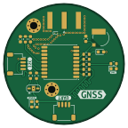
About the MAX-M10 GPS PCB
MAX-M10 GPS is an open source PCB design by vk-sahni, published on GitHub. It is a 4-layer board measuring 36 × 36 mm, with 22 components from 16 distinct parts.
Other key parts include the MAX-M10S. By type, the board carries 10 resistors, 4 diodes, 3 connectors, 2 capacitors, 1 IC and 1 battery holder.
It belongs with the rf & radio and dev boards & breakouts designs in this gallery.
From the project
Circular u-blox MAX-M10S GNSS receiver breakout with SMA antenna input, UART, I2C, backup-cell support, and KiCad design files.
A KiCad hardware design for a compact GNSS receiver based on the u-blox MAX-M10S module. The circular board brings out UART and I2C host interfaces, an SMA RF connector for an external GNSS antenna, a backup-cell footprint, and a PPS timing signal.
Rendered from MAX-M10GPS.step` (colored mechanical model).
The annotations identify board features and connectors. Connector pin numbering below follows the schematic/netlist; confirm pin 1 against the PCB silkscreen before wiring.

Main components on the MAX-M10 GPS
MAX-M10 GPS bill of materials (BOM)
22 components, 16 distinct parts — part numbers from the project's BOM.
| Qty | Part | Footprint | Refs |
|---|---|---|---|
| 1 | MAX-M10S | ublox_MAX | U1 |
| 1 | CON-SMA-EDGE-S | SMA_Amphenol_132289_EdgeMount | J1 |
| 2 | I2C | JST_SH_SM04B-SRSS-TB_1x04-1MP_P1.00mm_Horizontal | J2, J3 |
| 1 | ML414H_IV01E | SEIKO_ML414H_IV01E | BT2 |
| 1 | RED | LED_0603_1608Metric | D1 |
| 1 | ESD9B3.3ST5G | D_SOD-923 | D2 |
| 1 | GREEN | LED_0603_1608Metric | D3 |
| 1 | 0.5A/40V/420MA 0.5A/40V/420mA | D_0603_1608Metric | D4 |
| 1 | 2.66R | L_0603_1608Metric | L1 |
| 1 | C_Small | C_0603_1608Metric | C1 |
| 1 | 0.1UF 0.1uF | C_0603_1608Metric | C2 |
| 4 | 33R | R_0603_1608Metric | R3, R4, R5, R6 |
| 2 | 2.2K | R_0603_1608Metric | R9, R10 |
| 1 | TBD | R_0603_1608Metric | R11 |
| 2 | 1K | R_0603_1608Metric | R12, R13 |
| 1 | 3.3K | R_0603_1608Metric | R14 |
MAX-M10 GPS design files
The KiCad project lives in the vk-sahni/MAX-M10_GPS repository on GitHub; these links point at the commit this page was built from.
MAX-M10 GPS: common questions
How big is the MAX-M10 GPS PCB?
The MAX-M10 GPS measures 36 × 36 mm, has 4 copper layers and is 1.6 mm thick.
How many components are on the MAX-M10 GPS?
22 components, from 16 distinct parts, with part numbers taken from the project's own BOM. The full bill of materials is listed on this page.
Where can I download the MAX-M10 GPS design files?
From the vk-sahni/MAX-M10_GPS repository on GitHub, which has the KiCad layout, the schematic and the BOM; the links under Design files point to each one.
Can I use the MAX-M10 GPS design in my own project?
The repository has no license, so all rights stay with vk-sahni. Use it as a reference, and ask the author before reusing the design.
Similar boards
Breakout 112pin Connector
rusefi
174 × 58 mm39 parts2LGPL-3.01.2k
Eecv breakout
140.8 × 53.7 mm9 parts4LGPL-3.01.2k
Breakout 60pin EEC-IV
139.7 × 62.2 mm15 parts2LGPL-3.01.2k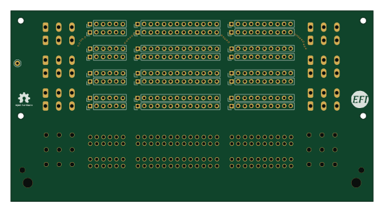
134pin 7-967288-1
139.7 × 73.7 mm38 parts2LGPL-3.01.2k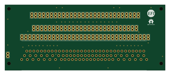
88 Pin Vag Breakout
142 × 58 mm91 parts2LGPL-3.01.2k
Rj45 breakout
rene-dev
15.2 × 53.8 mm3 parts2LGPL-3.0979