
40 pins PCB tester

About the 40 pins PCB tester
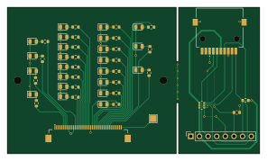
40 pins PCB tester is an open source PCB design by vroland, published on GitHub under the CC-BY-SA-4.0 license. It is a 2-layer board measuring 74 × 43 mm, with 51 components from 22 distinct parts.
Other key parts include the C841192. By type, the board carries 26 resistors, 16 diodes, 7 LEDs, 1 IC and 1 connector.
From the project
Hardware design files for EPDiy: https://github.com/vroland/epdiy.
This PCB is just a tester that comes handy if you want to check that all GPIOs, the 16 data lines plus other 7 signals, are correctly soldered in your PCB. After this comes just need to make a easy program, put all GPIOs in an array, and sequence them HIGH/ LOW.
NOTE: This needs a 40 pin Reversed cable in order to be connected to epdiy v7
Additionally in the 2nd panel has a small MicroSD raw adapter with the pin-out since it's really cheap to have one and at the same time of doing this tester, I wanted to research a way to add MicroSD support to an epdiy PCB.
Main components on the 40 pins PCB tester
40 pins PCB tester bill of materials (BOM)
51 components, 22 distinct parts — part numbers from the project's BOM.
| Qty | Part | Footprint | Refs |
|---|---|---|---|
| 1 | C841192 ED078KH6 | FH1240S05SH55 | U1 |
| 1 | XKTF-005 | XKTF005-SD | J1 |
| 7 | LED RED | LED_0805_2012Metric | CKV1, EP_MODE1, LEH1, OE1, STV1, XCL1, XSTL1 |
| 4 | LED GREEN | LED_0805_2012Metric | D0, D13, D14, D15 |
| 9 | C21353 LED GREEN | LED_0805_2012Metric | D1, D2, D3, D4, D5, D6, D7, D11 +1 |
| 1 | C2297 LED GREEN | LED_0805_2012Metric | D8 |
| 1 | C84256 LED GREEN | LED_0805_2012Metric | D9 |
| 1 | C8598 LED GREEN | LED_0805_2012Metric | D10 |
| 9 | C25804 2.4k | R_0603_1608Metric | R1, R4, R6, R10, R11, R12, R14, R15 +1 |
| 2 | C23186 2.4k | R_0603_1608Metric | R2, R7 |
| 2 | C21190 2.4k | R_0603_1608Metric | R3, R8 |
| 1 | C21189 2.4k | R_0603_1608Metric | R5 |
| 1 | C23212 2.4k | R_0603_1608Metric | R9 |
| 2 | C308324 2.4k | R_0603_1608Metric | R13, R17 |
| 1 | C23172 2.4k | R_0603_1608Metric | R18 |
| 2 | C22935 2.4k | R_0603_1608Metric | R19, R23 |
| 1 | C23196 2.4k | R_0603_1608Metric | R20 |
| 1 | C25822 2.4k | R_0603_1608Metric | R21 |
| 1 | C22807 2.4k | R_0603_1608Metric | R22 |
| 1 | C25819 33k | R_0603_1608Metric | R24 |
Show 2 more
| Qty | Part | Footprint | Refs |
|---|---|---|---|
| 1 | C4216 33k | R_0603_1608Metric | R25 |
| 1 | C425297 R_arr 35K Ω | SMT_F392JTCE_UNR_SD-pullup | RN1 |
40 pins PCB tester design files
The KiCad project lives in the vroland/epdiy-hardware repository on GitHub; these links point at the commit this page was built from.
40 pins PCB tester: common questions
How big is the 40 pins PCB tester?
The 40 pins PCB tester measures 74 × 43 mm, has 2 copper layers and is 1.6 mm thick.
How many components are on the 40 pins PCB tester?
51 components, from 22 distinct parts, with part numbers taken from the project's own BOM. The full bill of materials is listed on this page.
Where can I download the 40 pins PCB tester design files?
From the vroland/epdiy-hardware repository on GitHub, which has the KiCad layout, the schematic and the BOM; the links under Design files point to each one.
Can I use the 40 pins PCB tester design in my own project?
Yes, under the terms of its CC-BY-SA-4.0 license, which vroland chose for the repository.
More boards in epdiy-hardware
 ESP32
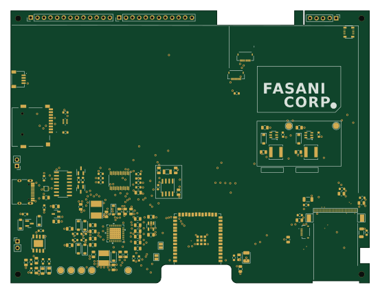
ESP32Kaleido 6" controller based on epdiy v7
138.1 × 104.6 mm121 parts4LCC-BY-SA-4.073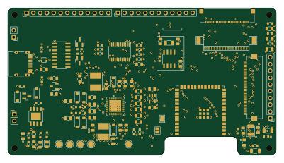 ESP32
ESP32Epdiy v7
100 × 55 mm108 parts4LCC-BY-SA-4.073 ESP32
ESP32Epdiy v7
128.4 × 74.9 mm105 parts4LCC-BY-SA-4.073
Charger stepup
31.1 × 16.1 mm19 parts2LCC-BY-SA-4.073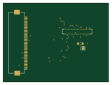
40 to WP27D-P050VA3
40 × 30 mm3 parts2LCC-BY-SA-4.073