
DebugVCFSeparate

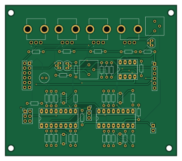
About the DebugVCFSeparate PCB
DebugVCFSeparate is an open source PCB design by wakimizufu, published on GitHub. It is a 2-layer board measuring 90 × 79 mm, with 54 components from 41 distinct parts.
Other key parts include the LM13700 and Opamp_Dual. By type, the board carries 32 resistors, 5 connectors, 5 capacitors, 3 ICs and 3 transistors.
Main components on the DebugVCFSeparate
DebugVCFSeparate bill of materials (BOM)
54 components, 41 distinct parts — part numbers from the project's BOM.
| Qty | Part | Footprint | Refs |
|---|---|---|---|
| 2 | LM13700 | DIP-16_W7.62mm_Socket_LongPads | U1, U2 |
| 1 | Opamp_Dual | DIP-8_W7.62mm_Socket_LongPads | U3 |
| 2 | Q_PNP_ECB | TO-92_HandSolder | Q1, Q2 |
| 1 | Q_NPN_ECB | TO-92_HandSolder | Q4 |
| 1 | A_Power | PinHeader_1x06_P2.54mm_Vertical | J1 |
| 1 | Input | PinSocket_2x06_P2.54mm_Vertical | J2 |
| 1 | InResoWav | PinHeader_2x03_P2.54mm_Vertical | J3 |
| 1 | FltOrder | PinSocket_1x03_P2.54mm_Vertical | J4 |
| 1 | VCFOut | PinHeader_1x02_P2.54mm_Vertical | J5 |
| 1 | 3362P 100K | Potentiometer_Bourns_3386P_Vertical | RV1 |
| 1 | 3362P 50K | Potentiometer_Bourns_3386P_Vertical | RV2 |
| 3 | RK09D117000B 100KB | RK09D117000B | VR1, VR2, VR4 |
| 1 | RK09D117000B 100KA | RK09D117000B | VR3 |
| 1 | CL21A106KAYNNNE 250pF | C_Disc_D4.7mm_W2.5mm_P5.00mm | C1 |
| 3 | 250pF | C_Disc_D4.7mm_W2.5mm_P5.00mm | C2, C3, C4 |
| 1 | 10uF BP | C_Radial_D5.0mm_H5.0mm_P2.00mm | C8 |
| 1 | 0805W8F3302T5E 560 | R_Axial_DIN0204_L3.6mm_D1.6mm_P7.62mm_Horizontal | R1 |
| 1 | 0805W8F4703T5E 560 | R_Axial_DIN0204_L3.6mm_D1.6mm_P7.62mm_Horizontal | R2 |
| 1 | 0805W8F1002T5E 68K | R_Axial_DIN0204_L3.6mm_D1.6mm_P7.62mm_Horizontal | R3 |
| 1 | 0805W8F4702T5E 100K | R_Axial_DIN0204_L3.6mm_D1.6mm_P7.62mm_Horizontal | R4 |
Show 21 more
| Qty | Part | Footprint | Refs |
|---|---|---|---|
| 1 | 0805W8F1001T5E 100K | R_Axial_DIN0204_L3.6mm_D1.6mm_P7.62mm_Horizontal | R5 |
| 1 | 0805W8F6802T5E 10K | R_Axial_DIN0204_L3.6mm_D1.6mm_P7.62mm_Horizontal | R6 |
| 2 | 0805W8F4702T5E 560 | R_Axial_DIN0204_L3.6mm_D1.6mm_P7.62mm_Horizontal | R7, R8 |
| 3 | 68K | R_Axial_DIN0204_L3.6mm_D1.6mm_P7.62mm_Horizontal | R9, R14, R24 |
| 1 | 390K 10K | R_Axial_DIN0204_L3.6mm_D1.6mm_P7.62mm_Horizontal | R10 |
| 1 | 470K 100K | R_Axial_DIN0204_L3.6mm_D1.6mm_P7.62mm_Horizontal | R11 |
| 1 | 470K 560 | R_Axial_DIN0204_L3.6mm_D1.6mm_P7.62mm_Horizontal | R12 |
| 2 | 560 | R_Axial_DIN0204_L3.6mm_D1.6mm_P7.62mm_Horizontal | R13, R18 |
| 3 | 10K | R_Axial_DIN0204_L3.6mm_D1.6mm_P7.62mm_Horizontal | R15, R23, R30 |
| 1 | 0805W8F1002T5E 100K | R_Axial_DIN0204_L3.6mm_D1.6mm_P7.62mm_Horizontal | R16 |
| 1 | 0805W8F1004T5E 560 | R_Axial_DIN0204_L3.6mm_D1.6mm_P7.62mm_Horizontal | R17 |
| 1 | 27K | R_Axial_DIN0204_L3.6mm_D1.6mm_P7.62mm_Horizontal | R19 |
| 2 | 100K | R_Axial_DIN0204_L3.6mm_D1.6mm_P7.62mm_Horizontal | R20, R31 |
| 1 | 1K | R_Axial_DIN0204_L3.6mm_D1.6mm_P7.62mm_Horizontal | R21 |
| 1 | 47K | R_Axial_DIN0204_L3.6mm_D1.6mm_P7.62mm_Horizontal | R22 |
| 1 | 56K | R_Axial_DIN0204_L3.6mm_D1.6mm_P7.62mm_Horizontal | R25 |
| 1 | 39K | R_Axial_DIN0204_L3.6mm_D1.6mm_P7.62mm_Horizontal | R26 |
| 1 | 20K | R_Axial_DIN0204_L3.6mm_D1.6mm_P7.62mm_Horizontal | R27 |
| 1 | 33K | R_Axial_DIN0204_L3.6mm_D1.6mm_P7.62mm_Horizontal | R28 |
| 1 | 150K | R_Axial_DIN0204_L3.6mm_D1.6mm_P7.62mm_Horizontal | R29 |
| 1 | 0805W8F2003T5E 10K | R_Axial_DIN0204_L3.6mm_D1.6mm_P7.62mm_Horizontal | R39 |
DebugVCFSeparate design files
The KiCad project lives in the wakimizufu/MC2 repository on GitHub; these links point at the commit this page was built from.
DebugVCFSeparate: common questions
How big is the DebugVCFSeparate PCB?
The DebugVCFSeparate measures 90 × 79 mm, has 2 copper layers and is 1.6 mm thick.
How many components are on the DebugVCFSeparate?
54 components, from 41 distinct parts, with part numbers taken from the project's own BOM. The full bill of materials is listed on this page.
Where can I download the DebugVCFSeparate design files?
From the wakimizufu/MC2 repository on GitHub, which has the KiCad layout, the schematic and the BOM; the links under Design files point to each one.
Can I use the DebugVCFSeparate design in my own project?
The repository has no license, so all rights stay with wakimizufu. Use it as a reference, and ask the author before reusing the design.
More boards in MC2
 PIC
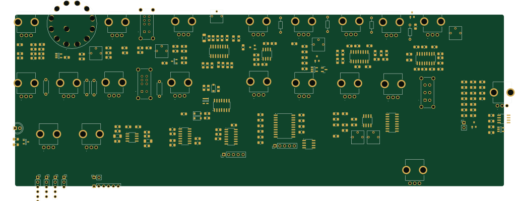
SynthBoard Left Rotary
257 × 90.2 mm229 parts2LNo license1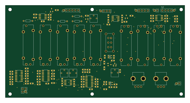 PIC
SynthBoard
155 × 80 mm123 parts2LNo license1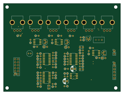
VCFSeparate
100 × 75 mm82 parts2LNo license1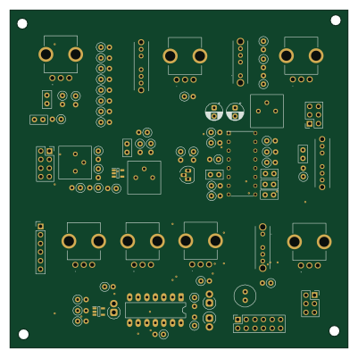
VCOSeparate
100 × 100 mm81 parts2LNo license1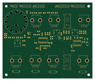
VCOBoard
100 × 85 mm80 parts2LNo license1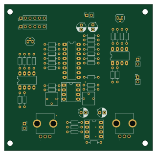
DebugVCASeparate
80 × 79 mm55 parts2LNo license1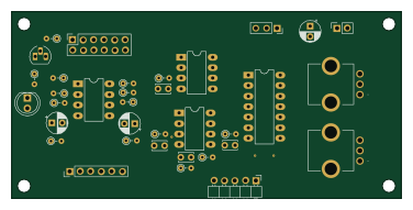 PIC
LFOSeparate
94 × 45 mm40 parts2LNo license1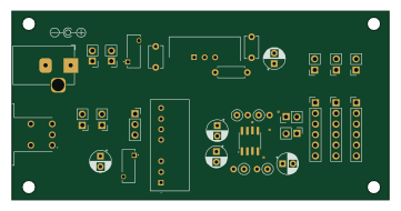
PowerSeparate
90 × 45 mm32 parts2LNo license1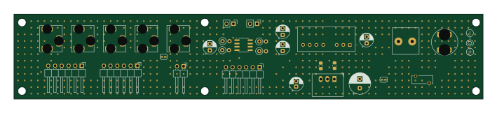
PowerAndJack
177 × 32.1 mm29 parts2LNo license1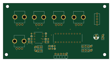 PIC
EGSeparate
99 × 52 mm26 parts2LNo license1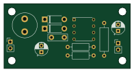
NJM2374A Invert
49 × 25 mm12 parts2LNo license1