
16 bit analog out

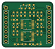
About the 16 bit analog out PCB
16 bit analog out is an open source PCB design by wntrblm, published on GitHub under the CC-BY-SA-4.0 license. It is a 2-layer board measuring 27.1 × 24 mm, with 29 components from 13 distinct parts.
Other key parts include the LM4040-10, AD5685R?RUZ and OPA4197. By type, the board carries 17 resistors, 6 capacitors, 3 ICs, 2 connectors and 1 inductor.
From the project
Re-usable test jig controller
Hubble is Winterbloom's re-usable development board for test jigs.
This repository contains the hardware design files and firmware files for Hubble.
- firmware/ contains the firmware source code, build scripts, and third-party dependencies. The firmware is written in C using GCC ARM. - hardware/ contains the hardware design files for the mainboard, jackboard, panel, and programming board. These are all created using KiCAD. - mechanical/ contains various designs for laser-cut and 3d-printed parts used to modify the stock test jig assembly for Hubble.
Main components on the 16 bit analog out
16 bit analog out bill of materials (BOM)
29 components, 13 distinct parts.
| Qty | Part | Footprint | Refs |
|---|---|---|---|
| 1 | LM4040-10 | SOT-23 | U1 |
| 1 | AD5685R?RUZ | TSSOP-16_4.4x5mm_P0.65mm | U2 |
| 1 | OPA4197 | TSSOP-14_4.4x5mm_P0.65mm | U3 |
| 1 | Inputs | PinHeader_1x08_P2.54mm_Vertical | J1 |
| 1 | Outputs | PinHeader_1x08_P2.54mm_Vertical | J2 |
| 1 | BEAD | L_0603_1608Metric_Pad1.05x0.95mm_HandSolder | FB1 |
| 1 | 1uF | C_0603_1608Metric_Pad1.08x0.95mm_HandSolder | C1 |
| 5 | 0.1uF | C_0603_1608Metric_Pad1.08x0.95mm_HandSolder | C2, C3, C4, C5, C6 |
| 1 | 270 | R_0603_1608Metric_Pad0.98x0.95mm_HandSolder | R1 |
| 4 | 1.54k | R_0603_1608Metric_Pad0.98x0.95mm_HandSolder | R2, R4, R6, R8 |
| 4 | 12.4k | R_0603_1608Metric_Pad0.98x0.95mm_HandSolder | R3, R5, R7, R9 |
| 4 | 10k | R_0603_1608Metric_Pad0.98x0.95mm_HandSolder | R10, R11, R12, R13 |
| 4 | 1k | R_0603_1608Metric_Pad0.98x0.95mm_HandSolder | R14, R15, R16, R17 |
16 bit analog out design files
The KiCad project lives in the wntrblm/Hubble repository on GitHub; these links point at the commit this page was built from.
16 bit analog out: common questions
How big is the 16 bit analog out PCB?
The 16 bit analog out measures 27.1 × 24 mm, has 2 copper layers and is 1.6 mm thick.
How many components are on the 16 bit analog out?
29 components, from 13 distinct parts. The full bill of materials is listed on this page.
Where can I download the 16 bit analog out design files?
From the wntrblm/Hubble repository on GitHub, which has the KiCad layout; the links under Design files point to each one.
Can I use the 16 bit analog out design in my own project?
Yes, under the terms of its CC-BY-SA-4.0 license, which wntrblm chose for the repository.
More boards in Hubble
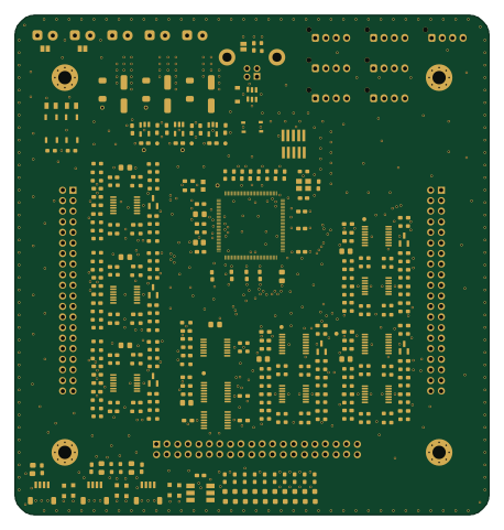 Microchip SAM
Hubble Motherboard
114 × 120 mm320 parts4LCC-BY-SA-4.023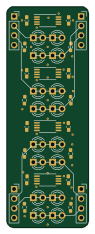
Leds
21.6 × 58.4 mm40 parts2LCC-BY-SA-4.023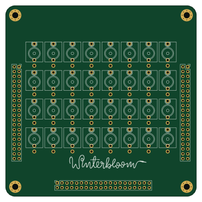
TestKit Adapter Template
100 × 100 mm35 parts2LCC-BY-SA-4.023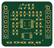
12-bit analog outputs
27.1 × 24 mm30 parts2LCC-BY-SA-4.023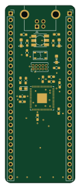 Microchip SAM
Mcu
26.9 × 68.6 mm27 parts2LCC-BY-SA-4.023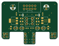
Power breakout
50.8 × 38.7 mm27 parts2LCC-BY-SA-4.023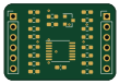
Analog in buffers
27.1 × 18.5 mm23 parts2LCC-BY-SA-4.023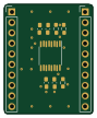
Analog Multiplexer
21.5 × 26.5 mm10 parts2LCC-BY-SA-4.023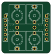
Jacks
26.7 × 27.9 mm6 parts2LCC-BY-SA-4.023