
UsbGpib

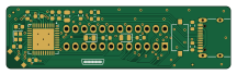
About the UsbGpib PCB
UsbGpib is an open source AVR/Arduino PCB design by xyphro, published on GitHub under the MIT license. It is a 2-layer board measuring 54 × 15 mm, with 21 components from 14 distinct parts.
Its main chip is the ATMEGA32U4-MU, from the AVR/Arduino family. By type, the board carries 8 resistors, 7 capacitors, 2 diodes, 1 IC, 1 crystal and 1 connector.
It belongs with the usb & debug tools designs in this gallery.
From the project
Versatile, cheap and portable USB to GPIB converter (USBTMC class based)
The new HW revision picks up some things that I and other misliked: - The REV 1 HW - when put beeing assembled into its housing did have change to colide with parts of the instruments body. Especially for Keysight equipment. This new HW revision follows the formfactor of an original GPIB cable to get rid of this mechanical constraint. - The REV 1 HW required to enter the bootloader with a tweezer. REV 2 has a button. Hold it a few seconds and the bootloader is entered.
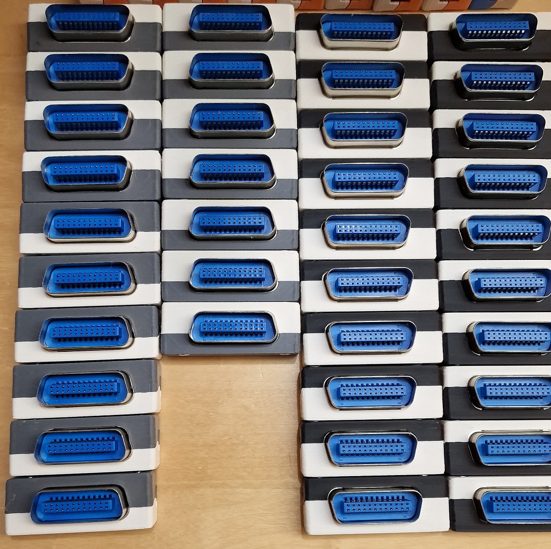
Main components on the UsbGpib
UsbGpib bill of materials (BOM)
21 components, 14 distinct parts — part numbers from the project's BOM.
| Qty | Part | Footprint | Refs |
|---|---|---|---|
| 1 | ATMEGA32U4-MU ATmega32U4-MU | QFN-44-1EP_7x7mm_P0.5mm_EP5.2x5.2mm | U1 |
| 1 | CX2016DB16000D0WZRC1 | Crystal_SMD_2016-4Pin_2.0x1.6mm | Y1 |
| 1 | USB_C_RECEPTACLE_USB2.0 USB_C_Receptacle_USB2.0 | USB_C_Receptacle_XKB_U262-16XN-4BVC11 | J1 |
| 1 | SW_Push | SW_Tactile_SPST_NO_Straight_CK_PTS636Sx25SMTRLFS | SW1 |
| 2 | LED | LED_0805_2012Metric | D1, D2 |
| 1 | 4.7UF 4.7uF | C_0805_2012Metric | C1 |
| 3 | 100NF 100nF | C_0603_1608Metric | C2, C3, C4 |
| 2 | 8PF 18pF | C_0603_1608Metric | C5, C6 |
| 1 | 1u | C_0603_1608Metric | C7 |
| 1 | 10K 10k | R_0603_1608Metric | R1 |
| 2 | 22R | R_0603_1608Metric | R2, R3 |
| 2 | 470R | R_0603_1608Metric | R4, R6 |
| 1 | 100K 100k | R_0603_1608Metric | R5 |
| 2 | 5K1 5k1 | R_0603_1608Metric | R7, R8 |
UsbGpib design files
The KiCad project lives in the xyphro/UsbGpib repository on GitHub; these links point at the commit this page was built from.
UsbGpib: common questions
What microcontroller does the UsbGpib use?
The UsbGpib is built around the ATMEGA32U4-MU, from the AVR/Arduino family.
How big is the UsbGpib PCB?
The UsbGpib measures 54 × 15 mm, has 2 copper layers and is 1.6 mm thick.
How many components are on the UsbGpib?
21 components, from 14 distinct parts, with part numbers taken from the project's own BOM. The full bill of materials is listed on this page.
Where can I download the UsbGpib design files?
From the xyphro/UsbGpib repository on GitHub, which has the KiCad layout, the schematic and the BOM; the links under Design files point to each one.
Can I use the UsbGpib design in my own project?
Yes, under the terms of its MIT license, which xyphro chose for the repository.
Can I test firmware for the UsbGpib without the hardware?
Yes. HardLabs builds a simulation of the board from its netlist and BOM, so you can run and debug AVR/Arduino firmware against it before you order a PCB.
Similar boards
 AVR/Arduino
V4
stuartpittaway
30 × 50 mm38 parts2LCC-BY-NC-4.01.1k AVR/Arduino
ModuleV450
30 × 61.4 mm39 parts2LCC-BY-NC-4.01.1k AVR/Arduino
Easyduino Atmega
Hanqaqa
68.8 × 53.6 mm35 parts4LCERN-OHL-P-2.0746 AVR/Arduino
Easyduino Atmega Nano
43.4 × 18 mm30 parts4LCERN-OHL-P-2.0746 AVR/Arduino
Lumberjack
peej
284.7 × 94.2 mm149 parts2LMIT402 AVR/Arduino
Chirp v2.4
Miceuz
140.8 × 16 mm19 partsNo license367