
BatteryPack

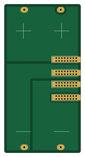
About the BatteryPack PCB
BatteryPack is an open source STM32 PCB design by zumizumi0625, published on GitHub. It is a 2-layer board measuring 40 × 78 mm, with 46 components from 33 distinct parts.
Its main chip is the STM32F030F4Px, from the STM32 family. Other key parts include the TP5100-Module and XC6206P332MR. By type, the board carries 17 connectors, 16 resistors, 6 diodes, 4 ICs, 2 capacitors and 1 battery holder.
It belongs with the power & battery designs in this gallery.
From the project
PCB設計の自動テスト CI/CD パイプライン(KiBot + ngspice + GitHub Actions)
KiCad で設計した基板を GitHub に push するだけで、回路のチェックとシミュレーションが自動で走る CI/CD パイプライン。
1. DRC(基板ルールチェック) — 配線間隔、ビア径、シルク被りなどの違反を検出 2. ERC(電気ルールチェック) — 未接続ピン、電源ショート、ネット名重複を検出 3. SPICE シミュレーション — 回路の電気的動作を自動検証 4. Discord 通知 — テスト結果をチャンネルに自動投稿 5. 製造ファイル生成 — Gerber、BOM、PDF、3D レンダー
テストが失敗したら波形画像も自動生成されて、Artifacts からダウンロードできる。
.github/workflows/pcb-ci.yml の冒頭で KiCad バージョンを指定する。2 箇所を揃えること:
Main components on the BatteryPack
BatteryPack bill of materials (BOM)
46 components, 33 distinct parts.
| Qty | Part | Footprint | Refs |
|---|---|---|---|
| 2 | TP5100-Module | TP5100-Module | U1, U4 |
| 1 | STM32F030F4Px | TSSOP-20_4.4x6.5mm_P0.65mm | U2 |
| 1 | XC6206P332MR | SOT-23 | U3 |
| 1 | Mirco USB | USB_Micro-B_Wuerth_629105150521_CircularHoles | J1 |
| 1 | B1+ | 2mm_Banana-Vertical | J2 |
| 1 | B1- | 2mm_Banana-Vertical | J3 |
| 1 | B2- | 2mm_Banana-Vertical | J4 |
| 1 | B2+ | 2mm_Banana-Vertical | J5 |
| 1 | CableConnector | Terminal_1x03_P5.08mm_Horizontal | J6 |
| 1 | SWD | PinHeader_1x05_P2.54mm_Vertical | J7 |
| 1 | UART | PinHeader_1x03_P2.54mm_Vertical | J8 |
| 1 | B2+ | 2mm_Banana-Socket | J9 |
| 1 | B1+ | 2mm_Banana-Socket | J10 |
| 1 | B1- | 2mm_Banana-Socket | J11 |
| 1 | B2- | 2mm_Banana-Socket | J12 |
| 1 | B1+ | 2mm_Banana-Plug | J13 |
| 1 | B1- | 2mm_Banana-Plug | J14 |
| 1 | B2+ | 2mm_Banana-Plug | J15 |
| 1 | B2- | 2mm_Banana-Plug | J16 |
| 1 | USB-C | USB_C_Female-16Pin-HPJF | P1 |
Show 13 more
| Qty | Part | Footprint | Refs |
|---|---|---|---|
| 1 | BK-18650-PC4 | BAT_BK-18650-PC4 | BT1 |
| 1 | LED_5V | LED_0603_1608Metric_Pad1.05x0.95mm_HandSolder | D1 |
| 1 | LED_9V | LED_0603_1608Metric_Pad1.05x0.95mm_HandSolder | D2 |
| 1 | LED_12V | LED_0603_1608Metric_Pad1.05x0.95mm_HandSolder | D3 |
| 1 | LED_40% | LED_0603_1608Metric_Pad1.05x0.95mm_HandSolder | D4 |
| 1 | LED_20% | LED_0603_1608Metric_Pad1.05x0.95mm_HandSolder | D5 |
| 1 | LED_0% | LED_0603_1608Metric_Pad1.05x0.95mm_HandSolder | D6 |
| 2 | 470n | C_0603_1608Metric_Pad1.05x0.95mm_HandSolder | C1, C2 |
| 5 | 10k | R_0603_1608Metric_Pad1.05x0.95mm_HandSolder | R1, R3, R9, R10, R12 |
| 2 | 2k4 | R_0603_1608Metric_Pad1.05x0.95mm_HandSolder | R2, R4 |
| 6 | 1k | R_0603_1608Metric_Pad1.05x0.95mm_HandSolder | R5, R6, R7, R14, R15, R16 |
| 1 | 62k | R_0603_1608Metric_Pad1.05x0.95mm_HandSolder | R8 |
| 2 | 20k | R_0603_1608Metric_Pad1.05x0.95mm_HandSolder | R11, R13 |
BatteryPack design files
The KiCad project lives in the zumizumi0625/PCB_Auto_test repository on GitHub; these links point at the commit this page was built from.
BatteryPack: common questions
What microcontroller does the BatteryPack use?
The BatteryPack is built around the STM32F030F4Px, from the STM32 family.
How big is the BatteryPack PCB?
The BatteryPack measures 40 × 78 mm, has 2 copper layers and is 1.6 mm thick.
How many components are on the BatteryPack?
46 components, from 33 distinct parts. The full bill of materials is listed on this page.
Where can I download the BatteryPack design files?
From the zumizumi0625/PCB_Auto_test repository on GitHub, which has the KiCad layout and the schematic; the links under Design files point to each one.
Can I use the BatteryPack design in my own project?
The repository has no license, so all rights stay with zumizumi0625. Use it as a reference, and ask the author before reusing the design.
Can I test firmware for the BatteryPack without the hardware?
Yes. HardLabs builds a simulation of the board from its netlist and BOM, so you can run and debug STM32 firmware against it before you order a PCB.
More boards in PCB_Auto_test
Similar boards
 STM32
LumenPnP Motherboard
opulo-inc
149 × 95 mm296 parts4LCC-BY-SA-4.03.7k STM32
Type g
google
169 × 30 mm24 parts2LApache-2.02.9k STM32
Base
52.3 × 52.3 mm36 parts2LApache-2.02.9k STM32
Main panel
234 × 84 mm26 parts4LApache-2.02.9k STM32
Type a
150 × 30 mm14 parts2LApache-2.02.9k STM32
Type c
188 × 30 mm17 parts2LApache-2.02.9k