
Nrsk right

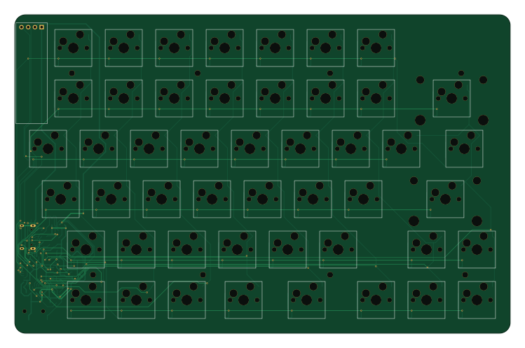
About the Nrsk right PCB
Nrsk right is an open source AVR/Arduino PCB design by 0x0c, published on GitHub. It is a 2-layer board measuring 187 × 120.3 mm, with 122 components from 65 distinct parts.
Its main chip is the ATmega32U4-AU, from the AVR/Arduino family. Other key parts include the USBLC6-2SC6. By type, the board carries 49 diodes, 48 switches, 9 resistors, 8 capacitors, 3 connectors and 2 ICs.
It belongs with the keyboards designs in this gallery.
From the project
KLE レイアウト(kle/left.json、kle/right.json)から生成した、左右分割・有線接続のキーボード基板です。 KiCad 10 のプロジェクト(回路図と配線済み基板)、製造用ガーバー、筐体(アクリルのレーザーカット用 DXF/SVG と 3D プリント用 STL)、BOM、QMK ファームウェア設定を含みます。
KLE レイアウト(kle/left.json、kle/right.json)から生成した、左右分割・有線接続のキーボード基板です。 KiCad 10 のプロジェクト(回路図と配線済み基板)、製造用ガーバー、筐体(アクリルのレーザーカット用 DXF/SVG と 3D プリント用 STL)、BOM、QMK ファームウェア設定を含みます。
v2 では Pro Micro などのマイコンボードをやめ、ATmega32U4 と USB-C コネクタなどを基板に直接実装しました。 マイコンボード用に設けていた内側の帯(約 20 mm)がなくなり、基板はキー領域とほぼ同じ大きさになっています。
各半分に同じ回路が載っています。ATmega32U4 の標準的な USB 接続回路に、保護部品を加えた構成です。
- ショットキーダイオードは逆流を防ぎます。TRRS で給電されている側の USB-C の VBUS には電圧が出ないので、両方の USB を挿してもホスト側に電流が逆流しません。USB を挿していない側が自分をマスターだと誤判定することもありません。 - ATmega32U4 は工場出荷時に DFU ブートローダーが書き込まれています。リセットスイッチを押すと、HWB のプルダウンによって DFU モードで起動し、USB 経由でファームウェアを書き込めます。ISP…
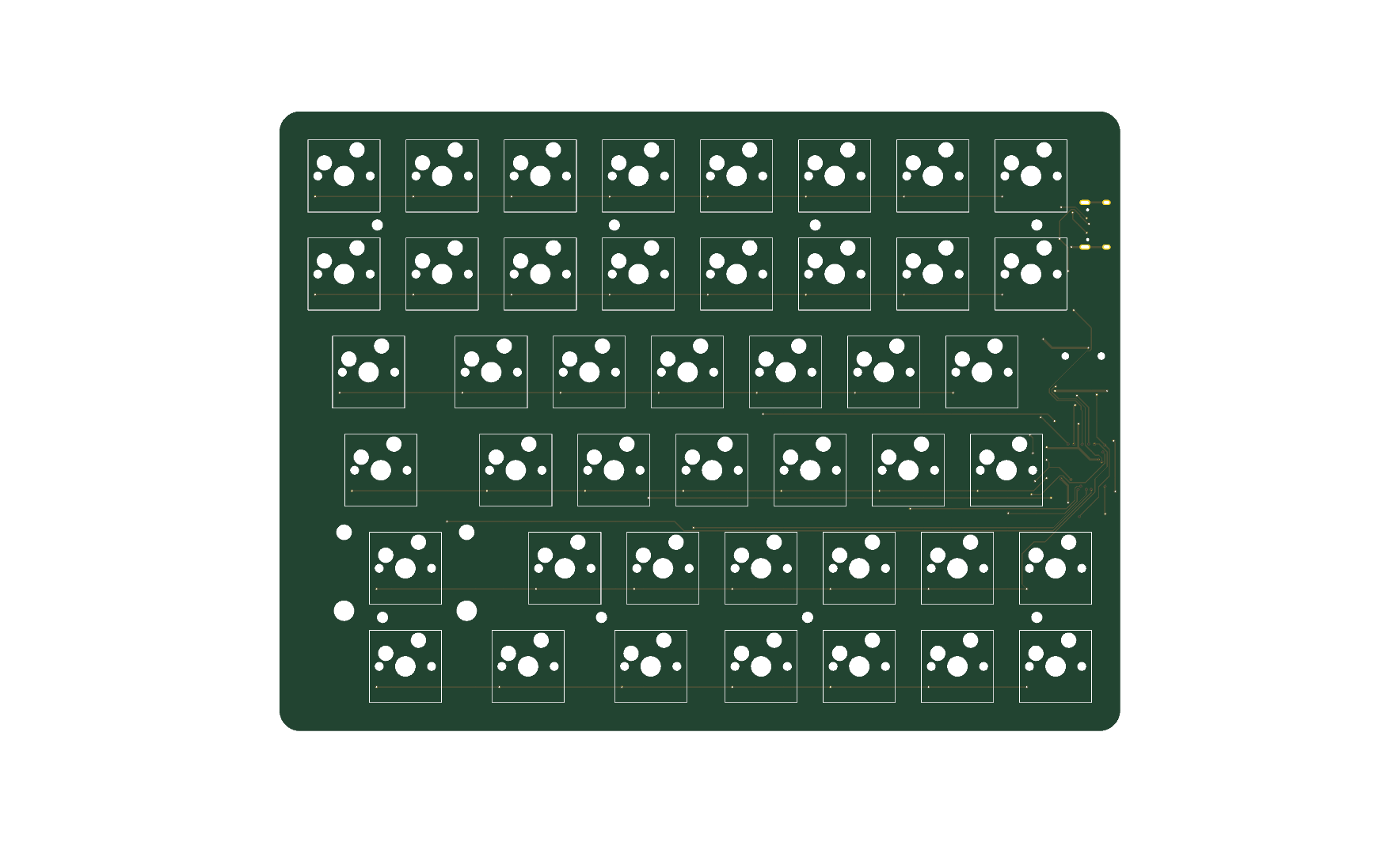
Main components on the Nrsk right
Nrsk right bill of materials (BOM)
122 components, 65 distinct parts.
| Qty | Part | Footprint | Refs |
|---|---|---|---|
| 1 | ATmega32U4-AU | TQFP-44_10x10mm_P0.8mm | U1 |
| 1 | USBLC6-2SC6 | SOT-23-6 | U2 |
| 1 | 16MHz | Crystal_SMD_3225-4Pin_3.2x2.5mm_HandSoldering | Y1 |
| 1 | PJ-320D | Jack_3.5mm_PJ320D_Horizontal | J1 |
| 1 | USB-C | USB_C_Receptacle_HRO_TYPE-C-31-M-12 | J2 |
| 1 | OLED 128x32 | OLED_0.91in_128x32_I2C | J3 |
| 1 | 500mA | Fuse_1206_3216Metric | F1 |
| 1 | Reset | SW_SPST_PTS810 | RSW1 |
| 1 | 71 | SW_MX_Hotswap_1.00u | SW1 |
| 1 | F7 | SW_MX_Hotswap_1.00u | SW2 |
| 1 | F8 | SW_MX_Hotswap_1.00u | SW3 |
| 1 | F9 | SW_MX_Hotswap_1.00u | SW4 |
| 1 | F10 | SW_MX_Hotswap_1.00u | SW5 |
| 1 | F11 | SW_MX_Hotswap_1.00u | SW6 |
| 1 | F12 | SW_MX_Hotswap_1.00u | SW7 |
| 1 | 73 | SW_MX_Hotswap_1.00u | SW8 |
| 1 | 7 | SW_MX_Hotswap_1.00u | SW9 |
| 1 | 8 | SW_MX_Hotswap_1.00u | SW10 |
| 1 | 9 | SW_MX_Hotswap_1.00u | SW11 |
| 1 | 0 | SW_MX_Hotswap_1.00u | SW12 |
Show 45 more
| Qty | Part | Footprint | Refs |
|---|---|---|---|
| 1 | - | SW_MX_Hotswap_1.00u | SW13 |
| 1 | = | SW_MX_Hotswap_1.00u | SW14 |
| 1 | Backspace | SW_MX_Hotswap_2.00u | SW15 |
| 1 | 75 | SW_MX_Hotswap_1.00u | SW16 |
| 1 | Y | SW_MX_Hotswap_1.00u | SW17 |
| 1 | U | SW_MX_Hotswap_1.00u | SW18 |
| 1 | I | SW_MX_Hotswap_1.00u | SW19 |
| 1 | O | SW_MX_Hotswap_1.00u | SW20 |
| 1 | P | SW_MX_Hotswap_1.00u | SW21 |
| 1 | [ | SW_MX_Hotswap_1.00u | SW22 |
| 1 | ] | SW_MX_Hotswap_1.00u | SW23 |
| 1 | \ | SW_MX_Hotswap_1.50u | SW24 |
| 1 | 77 | SW_MX_Hotswap_1.00u | SW25 |
| 1 | H | SW_MX_Hotswap_1.00u | SW26 |
| 1 | J | SW_MX_Hotswap_1.00u | SW27 |
| 1 | K | SW_MX_Hotswap_1.00u | SW28 |
| 1 | L | SW_MX_Hotswap_1.00u | SW29 |
| 1 | ; | SW_MX_Hotswap_1.00u | SW30 |
| 1 | ' | SW_MX_Hotswap_1.00u | SW31 |
| 1 | Enter | SW_MX_Hotswap_2.25u | SW32 |
| 1 | 79 | SW_MX_Hotswap_1.00u | SW33 |
| 1 | N | SW_MX_Hotswap_1.00u | SW34 |
| 1 | M | SW_MX_Hotswap_1.00u | SW35 |
| 1 | , | SW_MX_Hotswap_1.00u | SW36 |
| 1 | . | SW_MX_Hotswap_1.00u | SW37 |
| 1 | / | SW_MX_Hotswap_1.00u | SW38 |
| 1 | ↑ | SW_MX_Hotswap_1.00u | SW39 |
| 1 | fn | SW_MX_Hotswap_1.00u | SW40 |
| 1 | 81 | SW_MX_Hotswap_1.00u | SW41 |
| 2 | Space | SW_MX_Hotswap_1.00u | SW42, SW43 |
| 1 | Cmd | SW_MX_Hotswap_1.25u | SW44 |
| 1 | Opt | SW_MX_Hotswap_1.25u | SW45 |
| 1 | ← | SW_MX_Hotswap_1.00u | SW46 |
| 1 | ↓ | SW_MX_Hotswap_1.00u | SW47 |
| 1 | → | SW_MX_Hotswap_1.00u | SW48 |
| 48 | 1N4148W | D_SOD-123 | D1, D2, D3, D4, D5, D6, D7, D8 +40 |
| 1 | B5819W | D_SOD-123 | D99 |
| 2 | 22pF | C_0805_2012Metric | C1, C2 |
| 1 | 1uF | C_0805_2012Metric | C3 |
| 4 | 0.1uF | C_0805_2012Metric | C4, C5, C6, C7 |
| 1 | 10uF | C_0805_2012Metric | C8 |
| 3 | 10k | R_0805_2012Metric | R1, R6, R7 |
| 2 | 22 | R_0805_2012Metric | R2, R3 |
| 2 | 5.1k | R_0805_2012Metric | R4, R5 |
| 2 | 4.7k | R_0805_2012Metric | R8, R9 |
Nrsk right design files
The KiCad project lives in the 0x0c/spltnrskb repository on GitHub; these links point at the commit this page was built from.
- Layoutright/nrsk-right.kicad_pcb
- Schematicright/nrsk-right.kicad_sch
Nrsk right: common questions
What microcontroller does the Nrsk right use?
The Nrsk right is built around the ATmega32U4-AU, from the AVR/Arduino family.
How big is the Nrsk right PCB?
The Nrsk right measures 187 × 120.3 mm, has 2 copper layers and is 1.6 mm thick.
How many components are on the Nrsk right?
122 components, from 65 distinct parts. The full bill of materials is listed on this page.
Where can I download the Nrsk right design files?
From the 0x0c/spltnrskb repository on GitHub, which has the KiCad layout and the schematic; the links under Design files point to each one.
Can I use the Nrsk right design in my own project?
The repository has no license, so all rights stay with 0x0c. Use it as a reference, and ask the author before reusing the design.
Can I test firmware for the Nrsk right without the hardware?
Yes. HardLabs builds a simulation of the board from its netlist and BOM, so you can run and debug AVR/Arduino firmware against it before you order a PCB.
More boards in spltnrskb
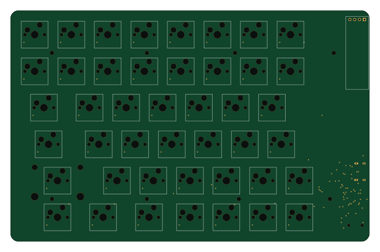
Similar boards
 AVR/Arduino
Redox keyboard
mattdibi
162.2 × 126.5 mm77 parts2LMIT2.0k AVR/Arduino
ModuleV450
stuartpittaway
30 × 61.4 mm39 parts2LCC-BY-NC-4.01.1k AVR/Arduino
V4
30 × 50 mm38 parts2LCC-BY-NC-4.01.1k AVR/Arduino
Discipline
coseyfannitutti
304.9 × 122.8 mm170 parts2LCC-BY-NC-4.01.0k AVR/Arduino
Megadesk
gcormier
41.7 × 32.2 mm23 parts2LGPL-3.0818 AVR/Arduino
Easyduino Atmega Nano
Hanqaqa
43.4 × 18 mm30 parts4LCERN-OHL-P-2.0746