
ClockSynthesizer

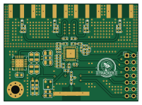
About the ClockSynthesizer PCB
ClockSynthesizer is an open source PCB design by AntonSievering, published on GitHub. It is a 4-layer board measuring 50.3 × 36.5 mm, with 66 components from 25 distinct parts.
Other key parts include the 584-ADF4351BCPZ-R7 and 595-TPS7A4700RGWR. By type, the board carries 28 capacitors, 25 resistors, 6 connectors, 3 diodes, 2 ICs and 1 transistor.
From the project
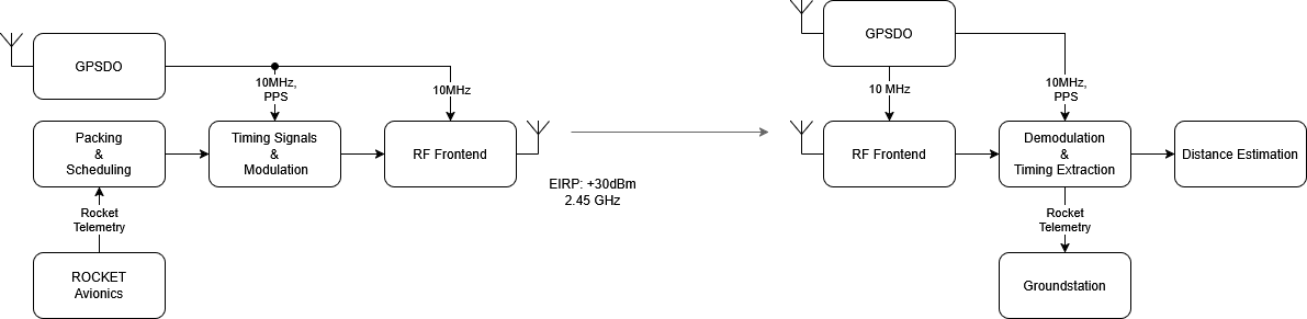
Sounding Rocket Tracking and Positioning Project
The rocket carries a transmitter that continuously downlinks telemetry along with timing signals. Multiple ground receivers (3–4 planned) receive the signal and extract the timing information. With the timing data, the system computes the rocket’s position in real time.
This repository contains the PCB projects for TRACKER - GPSDO-V2: 10 MHz oscillator tuned by the GPS timing signals - basestation-rx: S-band timing signal receiver - tracker-tx-fpga: FPGA baseboard with three subcarrier slots - tracker-subcarrier-adc: ADC subcarrier for FPGA baseboard - tracker-subcarrier-dac: DAC subcarrier…
Main components on the ClockSynthesizer
ClockSynthesizer bill of materials (BOM)
66 components, 25 distinct parts — part numbers from the project's BOM.
| Qty | Part | Footprint | Refs |
|---|---|---|---|
| 1 | 584-ADF4351BCPZ-R7 ADF4351 | LFCSP-32-1EP_5x5mm_P0.5mm_EP3.25x3.25mm | U1 |
| 1 | 595-TPS7A4700RGWR TPS7A4701xRGW | Texas_RGW0020A_VQFN-20-1EP_5x5mm_P0.65mm_EP3.15x3.15mm_ThermalVias | U2 |
| 1 | 637-MMFTN6001 MMFTN6001 | SOT-23 | Q1 |
| 5 | Conn_Coaxial | SMA_Amphenol_132289_EdgeMount | J1, J2, J3, J4, J5 |
| 1 | Conn_02x07_Counter_Clockwise | PinHeader_2x07_P2.54mm_Horizontal | J7 |
| 3 | LED | D_0603_1608Metric | D1, D2, D3 |
| 1 | 810-MLZ1608E100MT 10u | L_0603_1608Metric | L1 |
| 9 | 710-885012205086 100n | C_0402_1005Metric | C1, C4, C6, C9, C10, C11, C12, C13 +1 |
| 3 | 963-UMK105UJ100DV-F 10p | C_0402_1005Metric | C2, C3, C5 |
| 6 | 581-04023C102KAZ2A 1n | C_0402_1005Metric | C7, C8, C25, C26, C27, C28 |
| 4 | 963-LMK212BJ106KG-T 10u | C_0805_2012Metric | C15, C16, C17, C18 |
| 1 | 1u | C_0603_1608Metric | C19 |
| 2 | 81-GRM21BR61A476ME5L 47u | C_0805_2012Metric | C20, C21 |
| 1 | 80-C0402C182K5RAUTO 1n68 | C_0402_1005Metric | C22 |
| 1 | 81-GRM155R61A564ME5D 51n5 | C_0402_1005Metric | C23 |
| 1 | 603-AC0402JNPO9BN271 259p | C_0402_1005Metric | C24 |
| 1 | 603-AC0402JR-075K1L 5k1 | R_0402_1005Metric | R1 |
| 5 | 603-RT0402BRE0750RL 50 | R_0402_1005Metric | R2, R6, R7, R8, R9 |
| 1 | 652-CR0402-JW-271GLF 268 | R_0402_1005Metric | R3 |
| 1 | 652-CR0402-FX1691GLF 1k69 | R_0402_1005Metric | R4 |
Show 5 more
| Qty | Part | Footprint | Refs |
|---|---|---|---|
| 1 | 71-RCG0402100KJNED 100k | R_0402_1005Metric | R5 |
| 1 | 603-RC0402JR-7D100RL 100 | R_0402_1005Metric | R10 |
| 3 | 10k | R_0603_1608Metric | R11, R12, R13 |
| 8 | 652-CR0402-J/-000GLF 0 | R_0402_1005Metric | R14, R15, R16, R17, R18, R19, R20, R21 |
| 4 | 0 | R_0402_1005Metric | R22, R23, R24, R25 |
ClockSynthesizer design files
The KiCad project lives in the AntonSievering/TRACKER repository on GitHub; these links point at the commit this page was built from.
ClockSynthesizer: common questions
How big is the ClockSynthesizer PCB?
The ClockSynthesizer measures 50.3 × 36.5 mm, has 4 copper layers and is 1.6 mm thick.
How many components are on the ClockSynthesizer?
66 components, from 25 distinct parts, with part numbers taken from the project's own BOM. The full bill of materials is listed on this page.
Where can I download the ClockSynthesizer design files?
From the AntonSievering/TRACKER repository on GitHub, which has the KiCad layout, the schematic and the BOM; the links under Design files point to each one.
Can I use the ClockSynthesizer design in my own project?
The repository has no license, so all rights stay with AntonSievering. Use it as a reference, and ask the author before reusing the design.
More boards in TRACKER
 STM32
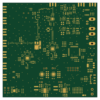
STM32Basestation rx-V2
100 × 100 mm292 parts4LNo license0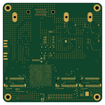 FPGA
FPGATracker tx fpga
100 × 100 mm224 parts6LNo license0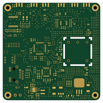 STM32
STM32GPSDO
100 × 100 mm179 parts4LNo license0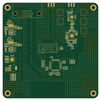 STM32
STM32Tracker tx
100 × 100 mm133 parts4LNo license0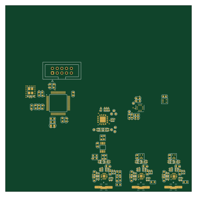 STM32
STM32Sampling scope
100 × 100 mm130 parts4LNo license0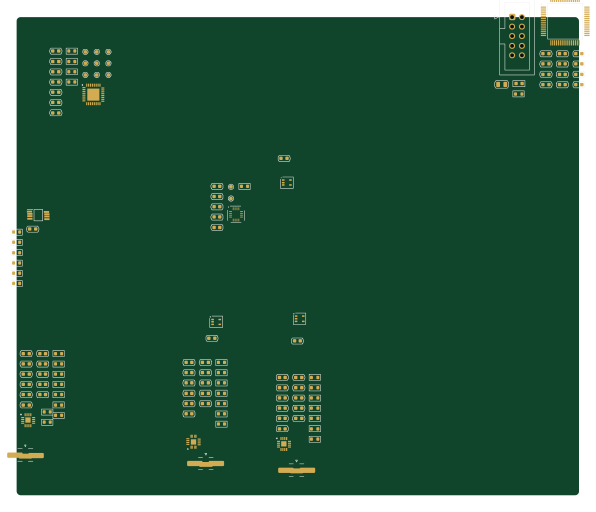 STM32
STM32Sampling scope-AntonsLaptop
148.8 × 126.5 mm112 parts4LNo license0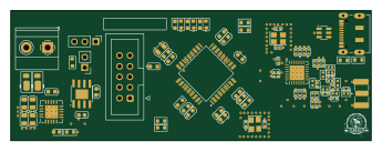 STM32
STM32Cc1200 comm
86.3 × 31 mm88 parts4LNo license0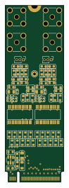
Tracker subcarrier dac
22 × 66 mm77 parts4LNo license0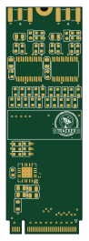
Tracker subcarrier adc
22 × 66 mm57 parts4LNo license0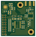
Digitizer
36 × 37.3 mm44 parts2LNo license0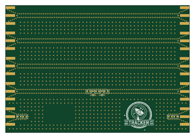
Testboard
100 × 69.2 mm19 parts4LNo license0