
Pwm breakout phat

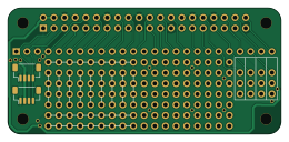
About the Pwm breakout phat
Pwm breakout phat is an open source PCB design by asssaf, published on GitHub. It is a 2-layer board measuring 65 × 30 mm, with 18 components from 7 distinct parts.
By type, the board carries 16 connectors, 1 IC and 1 jumper.
It belongs with the dev boards & breakouts and robotics & motion designs in this gallery.
From the project
A pHAT for Raspberry Pi, breaking out the PWM pins and some proto area
The PWM pins are broken out into four 3-pin connectors that can be used with 5V servos. Granted, it's not recommended to run a servo directly from the pi pins without any protection. But in practice, running micro servos (such as sg90), especially one at a time, should be ok (but do it at your own risk).
In order to enable hardware PWM, the appropriate overlay needs to be enabled in config.txt. For example:
Pwm breakout phat bill of materials (BOM)
18 components, 7 distinct parts.
| Qty | Part | Footprint | Refs |
|---|---|---|---|
| 1 | ~ | FourServos | U2 |
| 1 | GPIO | PinSocket_2x20_P2.54mm_Vertical | J1 |
| 3 | Conn_01x01 | NineConnectedPads | J2, J3, J4 |
| 1 | BO | PinSocket_1x25_P2.54mm_Vertical | J6 |
| 2 | Conn_01x04_Female | JST_SH_BM04B-SRSS-TB_1x04-1MP_P1.00mm_Vertical | J8, J9 |
| 9 | Conn_01x01 | ConnectedPads_01x04 | P1, P2, P3, P4, P5, P6, P7, P8 +1 |
| 1 | SolderJumper_3_Bridged12 | SolderJumper-3_P1.3mm_Bridged12_RoundedPad1.0x1.5mm | JP2 |
Pwm breakout phat design files
The KiCad project lives in the asssaf/pwm-breakout-phat repository on GitHub; these links point at the commit this page was built from.
- Layoutbreakout.kicad_pcb
- Schematicbreakout.kicad_sch
Pwm breakout phat: common questions
How big is the Pwm breakout phat?
The Pwm breakout phat measures 65 × 30 mm, has 2 copper layers and is 1.6 mm thick.
How many components are on the Pwm breakout phat?
18 components, from 7 distinct parts. The full bill of materials is listed on this page.
Where can I download the Pwm breakout phat design files?
From the asssaf/pwm-breakout-phat repository on GitHub, which has the KiCad layout and the schematic; the links under Design files point to each one.
Can I use the Pwm breakout phat design in my own project?
The repository has no license, so all rights stay with asssaf. Use it as a reference, and ask the author before reusing the design.
Similar boards

Stack chan
stack-chan
50 × 50 mm33 parts2LApache-2.01.7k
Breakout 60pin EEC-IV
rusefi
139.7 × 62.2 mm15 parts2LGPL-3.01.2k
134pin 7-967288-1
139.7 × 73.7 mm38 parts2LGPL-3.01.2k
Breakout 112pin Connector
174 × 58 mm39 parts2LGPL-3.01.2k
Eecv breakout
140.8 × 53.7 mm9 parts4LGPL-3.01.2k
88 Pin Vag Breakout
142 × 58 mm91 parts2LGPL-3.01.2k