
Motorspeed control

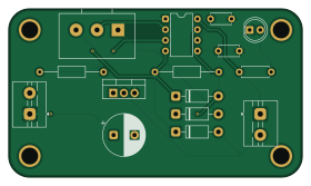
About the Motorspeed control PCB
Motorspeed control is an open source PCB design by baleshwarece-jpg, published on GitHub. It is a 2-layer board measuring 70 × 40 mm, with 15 components from 10 distinct parts.
Other key parts include the NE555P. By type, the board carries 4 diodes, 3 capacitors, 3 resistors, 2 connectors, 1 IC and 1 transistor.
From the project
30-Days-PCB-Design-Challenge
NE555P Timer IC TIP122 Transistor Diode (1N4007) Capacitor Resistor LED * Screw Terminals
Generates PWM signal for motor speed variation Adjustable motor speed control TIP122 handles higher motor current LED indicates power/status * Protection diode prevents back EMF damage
This project focuses on designing a motor speed control PCB using the NE555 timer IC for PWM generation. By adjusting the control input, the duty cycle changes, allowing smooth variation of DC motor speed. The TIP122 transistor acts as the driving stage for handling motor load efficiently. This project helped in…
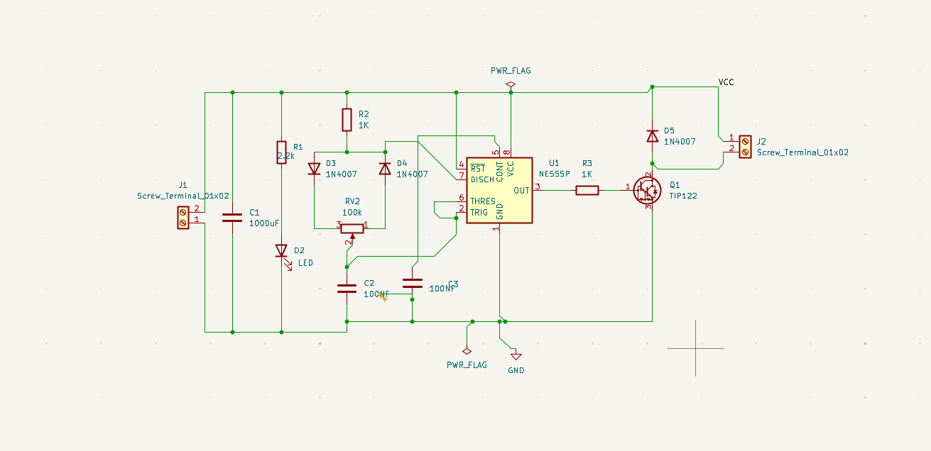
Main components on the Motorspeed control
Motorspeed control bill of materials (BOM)
15 components, 10 distinct parts.
| Qty | Part | Footprint | Refs |
|---|---|---|---|
| 1 | NE555P | DIP-8_W7.62mm | U1 |
| 1 | TIP122 | TO-220-3_Vertical | Q1 |
| 2 | Screw_Terminal_01x02 | TerminalBlock_MaiXu_MX126-5.0-02P_1x02_P5.00mm | J1, J2 |
| 1 | 100k | Potentiometer_Alps_RK163_Single_Horizontal | RV2 |
| 1 | LED | LED_D5.0mm | D2 |
| 3 | 1N4007 | D_DO-41_SOD81_P10.16mm_Horizontal | D3, D4, D5 |
| 1 | 1000uF | CP_Radial_D10.0mm_P5.00mm | C1 |
| 2 | 100NF | C_Disc_D4.7mm_W2.5mm_P5.00mm | C2, C3 |
| 1 | 2.2k | R_Axial_DIN0207_L6.3mm_D2.5mm_P7.62mm_Horizontal | R1 |
| 2 | 1K | R_Axial_DIN0207_L6.3mm_D2.5mm_P15.24mm_Horizontal | R2, R3 |
Motorspeed control design files
The KiCad project lives in the baleshwarece-jpg/PCB_PROJECTS repository on GitHub; these links point at the commit this page was built from.
Motorspeed control: common questions
How big is the Motorspeed control PCB?
The Motorspeed control measures 70 × 40 mm, has 2 copper layers and is 1.6 mm thick.
How many components are on the Motorspeed control?
15 components, from 10 distinct parts. The full bill of materials is listed on this page.
Where can I download the Motorspeed control design files?
From the baleshwarece-jpg/PCB_PROJECTS repository on GitHub, which has the KiCad layout and the schematic; the links under Design files point to each one.
Can I use the Motorspeed control design in my own project?
The repository has no license, so all rights stay with baleshwarece-jpg. Use it as a reference, and ask the author before reusing the design.
More boards in PCB_PROJECTS
74HC18
51.5 × 30 mm21 parts2LNo license0
Transformerless power supply
60 × 45 mm18 parts2LNo license0
WS2812B RGB LED Strip Driver
49 × 36 mm17 parts2LNo license0
Lm386 audio amplifier
55 × 35.3 mm12 parts2LNo license0
Audio day30
34 × 26.5 mm12 parts2LNo license0
Led batery indicator
80 × 20 mm12 parts2LNo license0
Discrete MOSFET H-Bridge
51 × 27 mm11 parts2LNo license0
MCP23017 — 16-bit I²C GPIO Expander
33 × 50 mm11 parts2LNo license0
Ac to dc
48 × 33.5 mm10 parts2LNo license0 AVR/Arduino
Arduino nano breakout board
45 × 80 mm8 parts2LNo license0
Max7219
48 × 36.5 mm7 parts2LNo license0