
Max7219

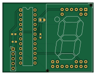
About the Max7219 PCB
Max7219 is an open source PCB design by baleshwarece-jpg, published on GitHub. It is a 2-layer board measuring 48 × 36.5 mm, with 7 components from 6 distinct parts.
Other key parts include the MAX7219. By type, the board carries 2 diodes, 2 capacitors, 1 IC, 1 connector and 1 resistor.
It belongs with the displays & leds designs in this gallery.
From the project
30-Days-PCB-Design-Challenge
Day 26 / 30 — 30-Day PCB Design Challenge
A driver board built around the MAX7219, which multiplexes and current-limits up to 8 digits of 7-segment LED displays (or a 64-LED dot matrix) from a single SPI-like 3-wire interface, eliminating the need to drive 64+ individual GPIO pins or external current-limiting resistors per segment.
Driving multiple 7-segment displays directly from a microcontroller requires either one GPIO per segment per digit (impractical past 1–2 digits) or a multiplexed scan routine where the MCU rapidly cycles through digits, sinking and sourcing current itself while…
Main components on the Max7219
Max7219 bill of materials (BOM)
7 components, 6 distinct parts.
| Qty | Part | Footprint | Refs |
|---|---|---|---|
| 1 | MAX7219 | DIP-24_W7.62mm | U1 |
| 1 | Conn_01x05_Pin | PinHeader_1x05_P2.54mm_Vertical | J1 |
| 1 | AD-121F2 | AD-121F2 | D1 |
| 1 | LED | LED_0805_2012Metric_Pad1.15x1.40mm_HandSolder | D2 |
| 2 | C | C_0603_1608Metric_Pad1.08x0.95mm_HandSolder | C1, C2 |
| 1 | R | R_0603_1608Metric_Pad0.98x0.95mm_HandSolder | R1 |
Max7219 design files
The KiCad project lives in the baleshwarece-jpg/PCB_PROJECTS repository on GitHub; these links point at the commit this page was built from.
Max7219: common questions
How big is the Max7219 PCB?
The Max7219 measures 48 × 36.5 mm, has 2 copper layers and is 1.6 mm thick.
How many components are on the Max7219?
7 components, from 6 distinct parts. The full bill of materials is listed on this page.
Where can I download the Max7219 design files?
From the baleshwarece-jpg/PCB_PROJECTS repository on GitHub, which has the KiCad layout and the schematic; the links under Design files point to each one.
Can I use the Max7219 design in my own project?
The repository has no license, so all rights stay with baleshwarece-jpg. Use it as a reference, and ask the author before reusing the design.
More boards in PCB_PROJECTS
74HC18
51.5 × 30 mm21 parts2LNo license0
Transformerless power supply
60 × 45 mm18 parts2LNo license0
WS2812B RGB LED Strip Driver
49 × 36 mm17 parts2LNo license0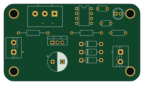
Motorspeed control
70 × 40 mm15 parts2LNo license0
Audio day30
34 × 26.5 mm12 parts2LNo license0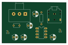
Lm386 audio amplifier
55 × 35.3 mm12 parts2LNo license0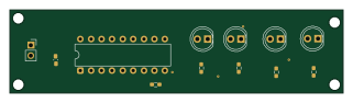
Led batery indicator
80 × 20 mm12 parts2LNo license0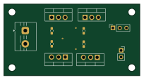
Discrete MOSFET H-Bridge
51 × 27 mm11 parts2LNo license0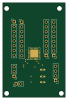
MCP23017 — 16-bit I²C GPIO Expander
33 × 50 mm11 parts2LNo license0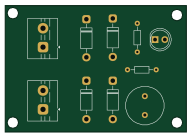
Ac to dc
48 × 33.5 mm10 parts2LNo license0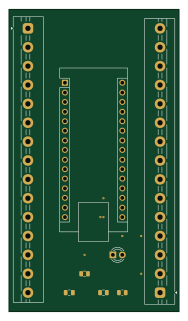 AVR/Arduino
Arduino nano breakout board
45 × 80 mm8 parts2LNo license0
Similar boards

LevelShifterBreakout
scottbez1
15.2 × 20.3 mm5 parts2LApache-2.022.2k
View base
81.2 × 81.2 mm81 parts2LApache-2.022.2k
View screen
35 × 35 mm12 parts2LApache-2.022.2k
BM28B0.6-24DSBreakout
15.2 × 35.6 mm3 parts2LApache-2.022.2k
ChainlinkDriverTester
198.1 × 95.3 mm123 parts2LApache-2.04.2k
ChainlinkBase
98.4 × 190.5 mm119 parts2LApache-2.04.2k