
Digital-Synchronous-Buck-Converter

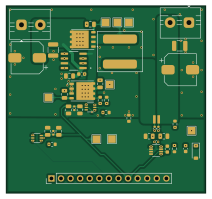
About the Digital-Synchronous-Buck-Converter PCB
Digital-Synchronous-Buck-Converter is an open source PCB design by BenjaminMeyerEE, published on GitHub. It is a 4-layer board measuring 52.8 × 49.6 mm, with 41 components from 26 distinct parts.
Other key parts include the BSC066N06NSATMA1 and INA241A3IDDFR. By type, the board carries 5 resistors, 3 ICs, 1 diode and 1 inductor.
It belongs with the power & battery designs in this gallery.
From the project
12 V to 6 V, 10 A synchronous buck converter with closed-loop digital control on an STM32G474RET6. Custom 4-layer board in KiCad. The firmware runs a 400 kHz PI voltage loop with hardware-enforced dead-time and a comparator overcurrent trip that doesn't depend on the CPU.
12 V to 6 V, 10 A synchronous buck converter with closed-loop digital control on an STM32G474RET6. Custom 4-layer board in KiCad. The firmware runs a 400 kHz PI voltage loop with hardware-enforced dead-time and a comparator overcurrent trip that doesn't depend on the CPU.
The power stage works. I've driven it from a function generator and from the test firmware in test-firmware/.
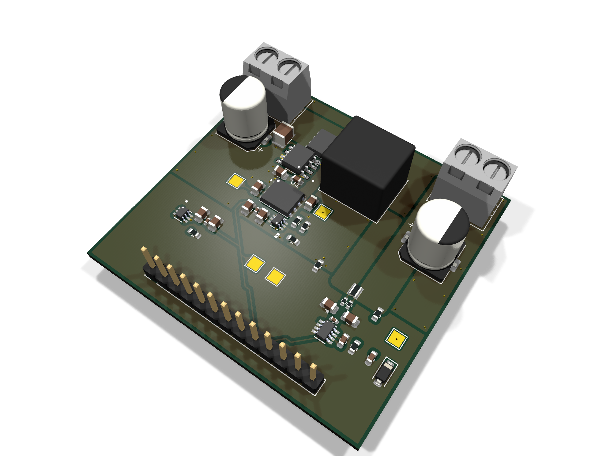
Main components on the Digital-Synchronous-Buck-Converter
Digital-Synchronous-Buck-Converter bill of materials (BOM)
41 components, 26 distinct parts — part numbers from the project's BOM.
| Qty | Part | Footprint | Refs |
|---|---|---|---|
| 2 | BSC066N06NSATMA1 | Infineon_PG-TDSON-8_6.15x5.15mm | U1, U2 |
| 1 | INA241A3IDDFR | SOT23-8_DDF_TEX | U3 |
| 1 | 47NF 47nF | C_0805_2012Metric | CB1 |
| 3 | 1uF | C_0805_2012Metric | C_DT_1U1, C_OC_1U1, C_UCC_VDD_HF1 |
| 2 | 10nF | C_0402_1005Metric | C_DT_10N1, C_OC_10N1 |
| 4 | 100pF | C_0805_2012Metric | C_DT_100P1, C_INA_FILT2, C_INA_FILT3, C_OC_100P1 |
| 1 | 1nF | C_0402_1005Metric | C_INA_FILT1 |
| 2 | 100nF | C_0603_1608Metric | C_INA_VCC1, C_UCC_VDD_LF1 |
| 2 | 10uF | C_1210_3225Metric | C_IN_HF1, C_OUT_HF1 |
| 2 | 47uF | CP_Elec_8x10 | C_IN_LF1, C_OUT_LF1 |
| 1 | 1nF | C_0603_1608Metric | C_VFB_FILT1 |
| 2 | Conn_01x02 | TerminalBlock_MaiXu_MX126-5.0-02P_1x02_P5.00mm | J_IN1, J_OUT1 |
| 1 | Conn_01x13 | PinHeader_1x13_P2.54mm_Vertical | J_STM1 |
| 2 | 10R | R_0402_1005Metric | R_FILT_N1, R_FILT_P1 |
| 2 | 10R | C_0805_2012Metric | R_GATE_1, R_GATE_2 |
| 2 | 75KR | R_0603_1608Metric | R_HYS1, R_HYS2 |
| 1 | 5mR | RES_2012_SUS | R_SHUNT1 |
| 2 | TLV3603DCKR-ET | SC70_DCK_TEX | U_DT1, U_OC1 |
| 1 | UCC27211D | SOIC127P599X175-8N | U_UCC1 |
| 1 | 3.3V | D_SOD-123 | D1 |
Show 6 more
| Qty | Part | Footprint | Refs |
|---|---|---|---|
| 1 | 6.8UH 6.8uH | L_Coilcraft_XAL1010-XXX | L1 |
| 1 | 0R | R_0603_1608Metric | R1 |
| 1 | 3.9KR | R_0603_1608Metric | R1_DT1 |
| 1 | 6.8KR | R_0603_1608Metric | R1_VFB1 |
| 1 | 1KR | R_0603_1608Metric | R2_DT1 |
| 1 | 10KR | R_0603_1608Metric | R2_VFB1 |
Digital-Synchronous-Buck-Converter design files
The KiCad project lives in the BenjaminMeyerEE/Digital-Synchronous-Buck-Converter repository on GitHub; these links point at the commit this page was built from.
Digital-Synchronous-Buck-Converter: common questions
How big is the Digital-Synchronous-Buck-Converter PCB?
The Digital-Synchronous-Buck-Converter measures 52.8 × 49.6 mm, has 4 copper layers and is 1.6 mm thick.
How many components are on the Digital-Synchronous-Buck-Converter?
41 components, from 26 distinct parts, with part numbers taken from the project's own BOM. The full bill of materials is listed on this page.
Where can I download the Digital-Synchronous-Buck-Converter design files?
From the BenjaminMeyerEE/Digital-Synchronous-Buck-Converter repository on GitHub, which has the KiCad layout, the schematic and the BOM; the links under Design files point to each one.
Can I use the Digital-Synchronous-Buck-Converter design in my own project?
The repository has no license, so all rights stay with BenjaminMeyerEE. Use it as a reference, and ask the author before reusing the design.
Similar boards

Stack chan
stack-chan
50 × 50 mm33 parts2LApache-2.01.7k
Display Carrier
AxxAxx
35.6 × 58.2 mm5 parts2LGPL-3.01.7k
ControllerCurrentShuntAddOn
stuartpittaway
26 × 16.9 mm9 parts2LCC-BY-NC-4.01.1k
Module 16S PassiveBalanceAddOn
61 × 74 mm86 parts2LCC-BY-NC-4.01.1k
TemperaturePCB PANEL
116 × 75.5 mm178 parts2LCC-BY-NC-4.01.1k
ProgrammingAdapter
10.5 × 83 mm3 parts2LCC-BY-NC-4.01.1k