
Boardoza Analog To PWM Converter Breakout Board

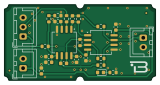
About the Boardoza Analog To PWM Converter Breakout Board
Boardoza Analog To PWM Converter Breakout Board is an open source PCB design by Boardoza, published on GitHub under the CC-BY-SA-4.0 license. It is a 2-layer board measuring 40 × 20 mm, with 24 components from 14 distinct parts.
Other key parts include the OPA2356AID and TLV3502AID. By type, the board carries 9 capacitors, 9 resistors, 3 connectors, 2 ICs and 1 diode.
It belongs with the dev boards & breakouts and robotics & motion designs in this gallery.
From the project
Hardware-based analog voltage to PWM signal converter breakout board with low-latency discrete analog architecture.
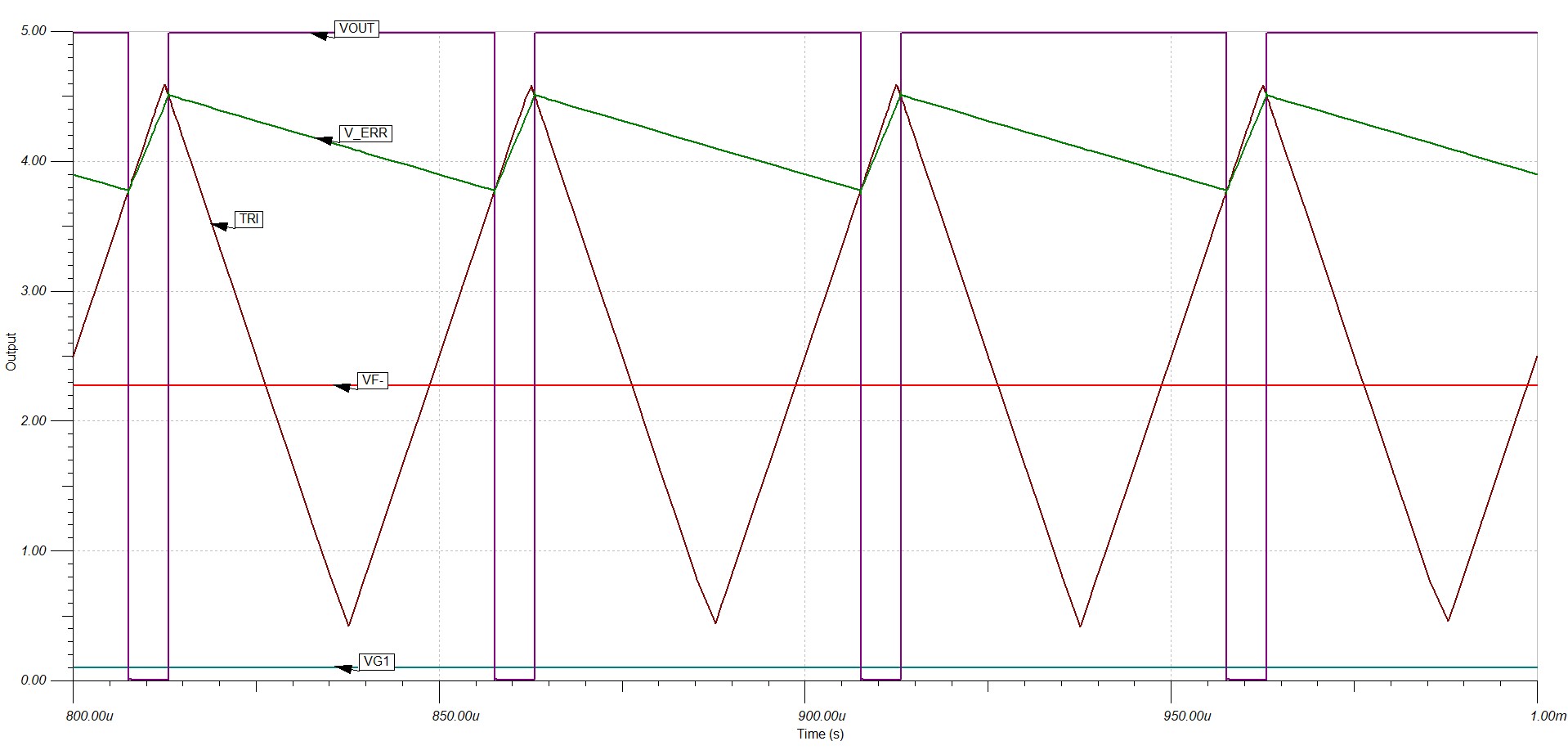
The Boardoza Analog to PWM Converter Breakout Board is a high-precision signal conditioning board designed to convert an analog voltage input into a proportional PWM (Pulse Width Modulation) output signal where the duty cycle increases or decreases proportionally with the applied input voltage. Built using high-speed operational amplifiers and comparators, this board operates entirely through dedicated hardware circuitry, enabling ultra-fast response times and reliable signal conversion without requiring any firmware or software processing.
Main components on the Boardoza Analog To PWM Converter Breakout Board
Boardoza Analog To PWM Converter Breakout Board bill of materials (BOM)
24 components, 14 distinct parts.
| Qty | Part | Footprint | Refs |
|---|---|---|---|
| 1 | OPA2356AID OPA2356xxD | SOIC-8_5.3x6.2mm_P1.27mm | U1 |
| 1 | TLV3502AID TLV3052AID | SOIC-8_5.3x6.2mm_P1.27mm | U2 |
| 1 | L-KLS1-2.50-03-SB Conn_01x03 | JST_XH_B3B-XH-A_1x03_P2.50mm_Vertical | J1 |
| 2 | L-KLS1-2.50-02-SB Conn_01x02 | JST_XH_B2B-XH-A_1x02_P2.50mm_Vertical | J2, J3 |
| 1 | LTST-C190KRKT LED | LED_0603_1608Metric | D1 |
| 1 | CL10C332JA8NNNC 3.3n | C_0603_1608Metric | C2 |
| 5 | CC0603KRX7R9BB104 100n | C_0603_1608Metric | C3, C4, C5, C7, C8 |
| 1 | CL10C222JB8NNNC 2.2n | C_0603_1608Metric | C6 |
| 1 | CL10A475KP8NNNC 4.7u | C_0603_1608Metric | C9 |
| 1 | CL10B105KO8NNNC 1u | C_0603_1608Metric | C10 |
| 3 | TC0350B1002T5F 10k | R_0603_1608Metric | R1, R3, R5 |
| 4 | TC0325D1001T5C 1k | R_0603_1608Metric | R4, R7, R8, R9 |
| 1 | RN73R1JTTD5831B25 5.83k | R_0603_1608Metric | R6 |
| 1 | ERJPB3B1102V 11k | R_0603_1608Metric | R10 |
Boardoza Analog To PWM Converter Breakout Board design files
The KiCad project lives in the Boardoza/Boardoza_Analog_To_PWM_Converter_Breakout_Board repository on GitHub; these links point at the commit this page was built from.
Boardoza Analog To PWM Converter Breakout Board: common questions
How big is the Boardoza Analog To PWM Converter Breakout Board?
The Boardoza Analog To PWM Converter Breakout Board measures 40 × 20 mm, has 2 copper layers and is 1.6 mm thick.
How many components are on the Boardoza Analog To PWM Converter Breakout Board?
24 components, from 14 distinct parts. The full bill of materials is listed on this page.
Where can I download the Boardoza Analog To PWM Converter Breakout Board design files?
From the Boardoza/Boardoza_Analog_To_PWM_Converter_Breakout_Board repository on GitHub, which has the KiCad layout and the schematic; the links under Design files point to each one.
Can I use the Boardoza Analog To PWM Converter Breakout Board design in my own project?
Yes, under the terms of its CC-BY-SA-4.0 license, which Boardoza chose for the repository.
Similar boards

Stack chan
stack-chan
50 × 50 mm33 parts2LApache-2.01.7k
Breakout 60pin EEC-IV
rusefi
139.7 × 62.2 mm15 parts2LGPL-3.01.2k
134pin 7-967288-1
139.7 × 73.7 mm38 parts2LGPL-3.01.2k
Breakout 112pin Connector
174 × 58 mm39 parts2LGPL-3.01.2k
Eecv breakout
140.8 × 53.7 mm9 parts4LGPL-3.01.2k
88 Pin Vag Breakout
142 × 58 mm91 parts2LGPL-3.01.2k