
Multi channel cremat amplifier

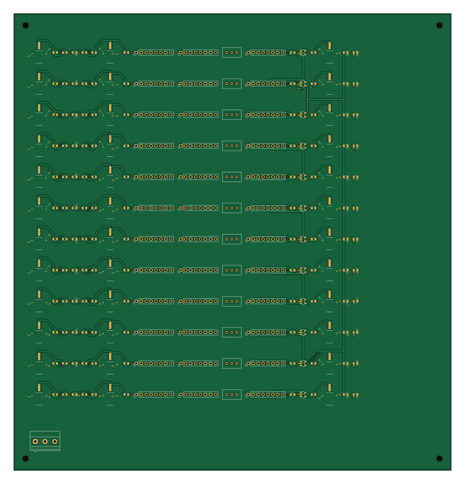
About the Multi channel cremat amplifier PCB
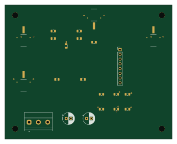
Multi channel cremat amplifier is an open source PCB design by Brunner-neutrino-lab, published on GitHub. It is a 4-layer board measuring 225 × 235 mm, with 216 components from 12 distinct parts.
Other key parts include the CR-112, CR-200-1us, CR-210 and EL5167. By type, the board carries 72 resistors, 48 ICs, 48 capacitors and 36 connectors.
It belongs with the audio and dev boards & breakouts designs in this gallery.
From the project
A 12-channel SiPM charge-sensitive preamplifier + Gaussian shaper board, derived from the Brunner-lab 6-channel Cremat CSP & Shaper board (cremat-x6-board) with four deliberate changes:
A 12-channel SiPM charge-sensitive preamplifier + Gaussian shaper board, derived from the Brunner-lab 6-channel Cremat CSP & Shaper board (cremat-x6-board) with four deliberate changes:
1. 12 channels (was 6). 2. 0805 passives wherever possible (was a mix of larger imperial sizes). 3. A Cremat CR-210 baseline restorer on every channel, optional — populate the module or an 0805 0R jumper to bypass it. 4. An on-board SiPM bias front-end on every channel: a BIASIN feed through an optional RC-in-series-with-R bias filter, then a node shared by the SiPM (DC-coupled) and the amplifier**…
Main components on the Multi channel cremat amplifier
Multi channel cremat amplifier bill of materials (BOM)
216 components, 12 distinct parts — part numbers from the project's BOM.
| Qty | Part | Footprint | Refs |
|---|---|---|---|
| 12 | CR-112 | PinHeader_1x08_P2.54mm_Vertical | U1, U5, U9, U13, U17, U21, U25, U29 +4 |
| 12 | CR-200-1us | PinHeader_1x08_P2.54mm_Vertical | U2, U6, U10, U14, U18, U22, U26, U30 +4 |
| 12 | CR-210 | PinHeader_1x08_P2.54mm_Vertical | U3, U7, U11, U15, U19, U23, U27, U31 +4 |
| 12 | EL5167 | SOT-23-5 | U4, U8, U12, U16, U20, U24, U28, U32 +4 |
| 36 | MCX CONMCX013 | MCX_CONMCX013_EdgeMount | J1, J2, J3, J4, J5, J6, J7, J8 +28 |
| 12 | 100k | Potentiometer_Bourns_3296W_Vertical | RV1, RV2, RV3, RV4, RV5, RV6, RV7, RV8 +4 |
| 12 | 100nF/100V | C_0805_2012Metric | C1, C5, C9, C13, C17, C21, C25, C29 +4 |
| 12 | 0.22uF/100V | C_0805_2012Metric | C2, C6, C10, C14, C18, C22, C26, C30 +4 |
| 24 | 100nF | C_0805_2012Metric | C3, C4, C7, C8, C11, C12, C15, C16 +16 |
| 24 | 10k | R_0805_2012Metric | R1, R3, R7, R9, R13, R15, R19, R21 +16 |
| 36 | 0R | R_0805_2012Metric | R2, R4, R5, R8, R10, R11, R14, R16 +28 |
| 12 | 49.9 | R_0805_2012Metric | R6, R12, R18, R24, R30, R36, R42, R48 +4 |
Multi channel cremat amplifier design files
The KiCad project lives in the Brunner-neutrino-lab/cremat-multi-channel-amplifier repository on GitHub; these links point at the commit this page was built from.
Multi channel cremat amplifier: common questions
How big is the Multi channel cremat amplifier PCB?
The Multi channel cremat amplifier measures 225 × 235 mm, has 4 copper layers and is 1.6 mm thick.
How many components are on the Multi channel cremat amplifier?
216 components, from 12 distinct parts, with part numbers taken from the project's own BOM. The full bill of materials is listed on this page.
Where can I download the Multi channel cremat amplifier design files?
From the Brunner-neutrino-lab/cremat-multi-channel-amplifier repository on GitHub, which has the KiCad layout, the schematic and the BOM; the links under Design files point to each one.
Can I use the Multi channel cremat amplifier design in my own project?
The repository has no license, so all rights stay with Brunner-neutrino-lab. Use it as a reference, and ask the author before reusing the design.
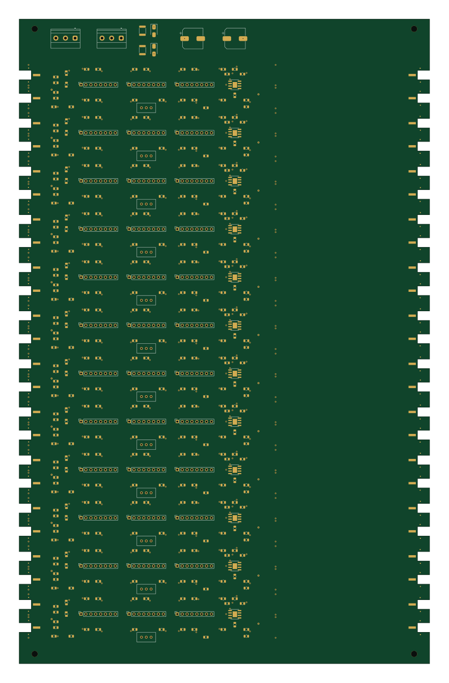
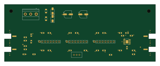
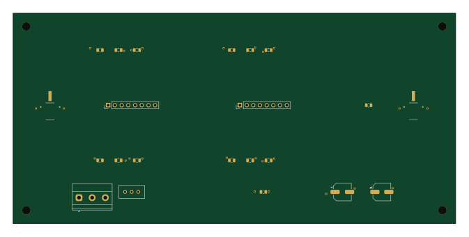
More boards in cremat-multi-channel-amplifier
Similar boards

Radioberry juice
pa3gsb
65 × 56 mm87 parts2LNo license675
Radioberry preamp
65 × 56 mm137 parts2LNo license675
Hat
65 × 56 mm81 parts2LNo license675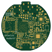
OtterCastAudioV2
Ottercast
50 × 49.3 mm216 parts4LMIT665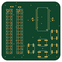
Sram dev board
Wren6991
50 × 50 mm12 parts2LNo license508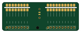
Connecting piece
Chrismettal
66.4 × 24.5 mm20 parts2LCC-BY-SA-4.0446