
Module-I2C-1.42-display

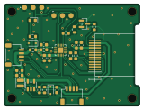
About the Module-I2C-1.42-display
Module-I2C-1.42-display is an open source RISC-V PCB design by buildwithnoknok, published on GitHub under the MIT license. It is a 2-layer board measuring 40 × 30 mm, with 28 components from 22 distinct parts.
Its main chip is the CH32V003F4U6, from the RISC-V family. Other key parts include the MT3540-F23. By type, the board carries 10 resistors, 8 capacitors, 3 diodes, 2 ICs, 2 connectors and 1 transistor.
It belongs with the displays & leds designs in this gallery.
From the project
noknok 1.42-inch color TFT display module (I2C). CH32V003 GPU + ER-TFT1.42-1 80x160 IPS panel (NV3022B), 4-wire SPI. In development.
The first assembled boards (July 2026) had the panel mounted mirrored: the noknokER-TFT1.42-113pinsolderproto footprint numbered its 13 pads backwards, so board pad n contacted panel pin 14-n. The panel's RES landed on GND (permanent reset), its VCC on the SCK line (never powered), and LEDA on a touch-NC pin.
Fixed in the Ecosystem library (commit cb83a33) — pad 1 is now on the +X end — and re-fabbed as rev 1.1. Bench boards were rescued by re-soldering the panel rotated 180° in the plane of the board, which is why rev 1.0 firmware carried a PANELROTATEDREWORK switch.
Main components on the Module-I2C-1.42-display
Module-I2C-1.42-display bill of materials (BOM)
28 components, 22 distinct parts — part numbers from the project's BOM.
| Qty | Part | Footprint | Refs |
|---|---|---|---|
| 1 | CH32V003F4U6 WCH | QFN-20-1EP_3x3mm_P0.4mm_EP1.65x1.65mm | U1 |
| 1 | MT3540-F23 MT3540‑F23 XI'AN Aerosemi Tech | SOT-23-5 | U2 |
| 1 | AO3400A 2N7002 or AO3400A (pin2pin) AOS | SOT-23 | Q1 |
| 2 | C160404 JST 4 Pin Qwiic I2C Connector JST | JST_SH_SM04B-SRSS-TB_1x04-1MP_P1.00mm_Horizontal | J1, J2 |
| 1 | ER-TFT1.42-1 noknok_ER-TFT1.42-1 EastRising | noknok_ER-TFT1.42-1_13pin_solder_proto | DS1 |
| 1 | MM3Z3V6T1G D_Zener onsemi | D_SOD-323 | D2 |
| 1 | NSR0320MW2T1G D_Schottky onsemi | D_SOD-323 | D3 |
| 1 | KT-0603R LED Hubei KENTO Elec | LED_0603_1608Metric | D4 |
| 1 | FTC252010S4R7MBCA Inductor 4.7uH cjiang | L_Changjiang_FTC252010S | L1 |
| 2 | CC0603MRX5R8BB106 10uF YAGEO | C_0603_1608Metric | C1, C7 |
| 4 | CC0603KRX7R9BB104 0.1uF YAGEO | C_0603_1608Metric | C2, C4, C5, C8 |
| 1 | CC1206KKX5R8BB226 22uF YAGEO | C_0603_1608Metric | C6 |
| 1 | CC0603KRX7R9BB105 1uF YAGEO | C_0603_1608Metric | C9 |
| 1 | RC0603JR-0710RL 10R YAGEO | R_0603_1608Metric | R1 |
| 1 | RC0603JR-0710KL 10k YAGEO | R_0603_1608Metric | R2 |
| 1 | RC0603JR-0733KL 33k YAGEO | R_0603_1608Metric | R3 |
| 1 | RC0603JR-0712KL 12k YAGEO | R_0603_1608Metric | R4 |
| 1 | RC0603JR-072K2L 2.2k YAGEO | R_0603_1608Metric | R5 |
| 2 | RC0603JR-0722RL 22R YAGEO | R_0603_1608Metric | R6, R7 |
| 1 | RC0603JR-0733RL 33R YAGEO | R_0603_1608Metric | R8 |
Show 2 more
| Qty | Part | Footprint | Refs |
|---|---|---|---|
| 1 | RC0603JR-07100KL 100k YAGEO | R_0603_1608Metric | R9 |
| 1 | RC0603JR-07100RL 100R YAGEO | R_0603_1608Metric | R10 |
Module-I2C-1.42-display design files
The KiCad project lives in the buildwithnoknok/module-I2C-1.42-display repository on GitHub; these links point at the commit this page was built from.
Module-I2C-1.42-display: common questions
What microcontroller does the Module-I2C-1.42-display use?
The Module-I2C-1.42-display is built around the CH32V003F4U6, from the RISC-V family.
How big is the Module-I2C-1.42-display?
The Module-I2C-1.42-display measures 40 × 30 mm, has 2 copper layers and is 1.6 mm thick.
How many components are on the Module-I2C-1.42-display?
28 components, from 22 distinct parts, with part numbers taken from the project's own BOM. The full bill of materials is listed on this page.
Where can I download the Module-I2C-1.42-display design files?
From the buildwithnoknok/module-I2C-1.42-display repository on GitHub, which has the KiCad layout, the schematic and the BOM; the links under Design files point to each one.
Can I use the Module-I2C-1.42-display design in my own project?
Yes, under the terms of its MIT license, which buildwithnoknok chose for the repository.
Can I test firmware for the Module-I2C-1.42-display without the hardware?
Yes. HardLabs builds a simulation of the board from its netlist and BOM, so you can run and debug RISC-V firmware against it before you order a PCB.
Similar boards
 RISC-V
Audio
byrantech
27.8 × 22.3 mm38 parts2LMIT4.3k RISC-V
Keybit
notaroomba
19.1 × 19.1 mm19 parts2LNo license438 RISC-V
Workbench-1 Controller
Quchaosheng
160 × 130 mm106 parts8LApache-2.0212 RISC-V
Froggyswadge
cnlohr
81.5 × 72.2 mm92 parts2LMIT105 RISC-V
Keytartouch
152.5 × 117.5 mm69 parts2LMIT105 RISC-V
Ch32v003f4u6 with wsled
40.6 × 44.5 mm26 parts2LMIT105