
F-Stop DarkRoomTimer

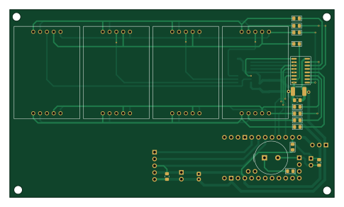
About the F-Stop DarkRoomTimer PCB
F-Stop DarkRoomTimer is an open source AVR/Arduino PCB design by c1rk1, published on GitHub under the BSD-3-Clause license. It is a 2-layer board measuring 121 × 70 mm, with 29 components from 15 distinct parts.
Its main chip is the Arduino_Pro_Mini, from the AVR/Arduino family. Other key parts include the SA10-21SRWA and 74AHC595. By type, the board carries 10 resistors, 7 capacitors, 6 ICs, 4 connectors, 1 module and 1 buzzer.
From the project
Simple to build, simple to use "F-Stop" DarkRoom Timer with develop timer
F- stop printing was originally made popular by the award winning printer Gene Nocon in 1987.
Menu options: En.-t. : Enlarger timer dE.-t. : Develop timer SEt.t. : Set time F-St. : f-stop set Stri. : Strip Zone : Zone expo
En.-t. : Enlarger timer - set the desired value with the rotary encoder (the steps can be set in "F-St." menu) START/Pause with the "Pedal button". Sound will be played on lamp ON and lamp OFF. Default value after power up 10 sec. (you can change it in "SEt.t." menu).
Main components on the F-Stop DarkRoomTimer
F-Stop DarkRoomTimer bill of materials (BOM)
29 components, 15 distinct parts.
| Qty | Part | Footprint | Refs |
|---|---|---|---|
| 4 | SA10-21SRWA | SA10-21SRWA_KNB | U1, U2, U3, U4 |
| 2 | 74AHC595 | SOIC-16_3.9x9.9mm_P1.27mm | U5, U6 |
| 1 | Arduino_Pro_Mini | Clone_Pro_Mini_Socket_NoSPH | A1 |
| 1 | Start Button | PinHeader_1x02_P2.54mm_Vertical | J1 |
| 1 | Power | PinHeader_1x02_P2.54mm_Vertical | J2 |
| 1 | Rotary Enc. | PinHeader_1x05_P2.54mm_Vertical | J3 |
| 1 | LampRelayBoard | PinHeader_1x03_P2.54mm_Vertical | J4 |
| 1 | Buzzer | Buzzer_TDK_PS1240P02BT_D12.2mm_H6.5mm | BZ1 |
| 4 | 100nF | C_0805_2012Metric_Pad1.18x1.45mm_HandSolder | C1, C2, C6, C7 |
| 2 | 22uF | C_1812_4532Metric_Pad1.57x3.40mm_HandSolder | C3, C4 |
| 1 | 100uF | CP_Radial_D5.0mm_P2.00mm | C5 |
| 7 | 330 | R_0805_2012Metric_Pad1.15x1.40mm_HandSolder | R1, R2, R3, R4, R5, R6, R7 |
| 1 | 660 | R_0805_2012Metric_Pad1.15x1.40mm_HandSolder | R8 |
| 1 | 5K1 | R_0805_2012Metric_Pad1.15x1.40mm_HandSolder | R9 |
| 1 | 100 | R_0805_2012Metric_Pad1.15x1.40mm_HandSolder | R10 |
F-Stop DarkRoomTimer design files
The KiCad project lives in the c1rk1/F-Stop_DarkRoomTimer repository on GitHub; these links point at the commit this page was built from.
F-Stop DarkRoomTimer: common questions
What microcontroller does the F-Stop DarkRoomTimer use?
The F-Stop DarkRoomTimer is built around the Arduino_Pro_Mini, from the AVR/Arduino family.
How big is the F-Stop DarkRoomTimer PCB?
The F-Stop DarkRoomTimer measures 121 × 70 mm, has 2 copper layers and is 1.6 mm thick.
How many components are on the F-Stop DarkRoomTimer?
29 components, from 15 distinct parts. The full bill of materials is listed on this page.
Where can I download the F-Stop DarkRoomTimer design files?
From the c1rk1/F-Stop_DarkRoomTimer repository on GitHub, which has the KiCad layout and the schematic; the links under Design files point to each one.
Can I use the F-Stop DarkRoomTimer design in my own project?
Yes, under the terms of its BSD-3-Clause license, which c1rk1 chose for the repository.
Can I test firmware for the F-Stop DarkRoomTimer without the hardware?
Yes. HardLabs builds a simulation of the board from its netlist and BOM, so you can run and debug AVR/Arduino firmware against it before you order a PCB.
Similar boards
 AVR/Arduino
Magspoof
samyk
35 × 29 mm11 parts2LNo license4.2k AVR/Arduino
Redox keyboard
mattdibi
162.2 × 126.5 mm77 parts2LMIT2.0k AVR/Arduino
Labrador
espotek-org
36.8 × 34.7 mm75 parts2LNo license1.2k AVR/Arduino
V4
stuartpittaway
30 × 50 mm38 parts2LCC-BY-NC-4.01.1k AVR/Arduino
ModuleV450
30 × 61.4 mm39 parts2LCC-BY-NC-4.01.1k AVR/Arduino
Discipline
coseyfannitutti
304.9 × 122.8 mm170 parts2LCC-BY-NC-4.01.0k