
Logic analyzer

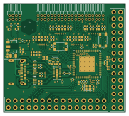
About the Logic analyzer PCB
Logic analyzer is an open source PCB design by cheyao, published on GitHub under the SHL-2.1 license. It is a 4-layer board measuring 45.2 × 40.4 mm, with 93 components from 20 distinct parts.
Other key parts include the CH32H417MEU6, AMS1117-3.3, LMV321IDCKT, TMUXHS4212RKSR and TPD4EUSB30DQAR. By type, the board carries 43 capacitors, 35 resistors, 7 ICs, 3 diodes, 2 switches and 1 crystal.
It belongs with the test & measurement and dev boards & breakouts designs in this gallery.
From the project
200MHz USB 3.1 logic analyzer and 20MHz ADC w/ pulseview
This is a cheap 200Msps logic analyzer with a 20Msps analog component. It uses USB 3.2 to send data to the computer, and can also act as a ch32h417 development board.
It is usable with pulseview delivering a beautiful interface and allowing you to view all kinds of diffrent protocols. And with voltage changing, it supports 1.2V, 3.3V and 5V opration modes.
The analog channels support 20Msps at 10bit accuracy, or 5MHz at 12bit accuracy. Input range is from 0V to 5V, and it supports external triggering too!
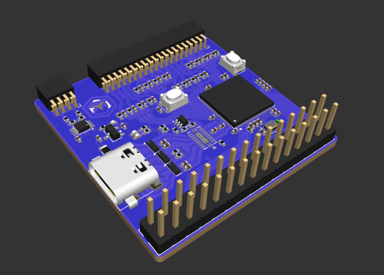
Main components on the Logic analyzer
Logic analyzer bill of materials (BOM)
93 components, 20 distinct parts — part numbers from the project's BOM.
| Qty | Part | Footprint | Refs |
|---|---|---|---|
| 1 | CH32H417MEU6 CH32H417MxUx | QFN-88-1EP_10x10mm_P0.4mm_EP5.7x5.7mm_ThermalVias | U1 |
| 1 | AMS1117-3.3 | SOT-89-3 | U2 |
| 1 | LMV321IDCKT LMV321 | SOT-353_SC-70-5 | U3 |
| 1 | TMUXHS4212RKSR TMUXHS4212 | DHVQFN-20-1EP_2.5x4.5mm_P0.5mm_EP1x3mm | U5 |
| 3 | TPD4EUSB30DQAR TPD4EUSB30 | USON-10_2.5x1.0mm_P0.5mm | U16, U22, U23 |
| 1 | XT1220HJRGX25M00E 25MHz 20pF | Crystal_SMD_2016-4Pin_2.0x1.6mm | Y1 |
| 1 | C2681555 USB_C_Receptacle | USB_C_Receptacle_SHOU-HAN_24P-QT | J1 |
| 1 | C46640991 1A@12V | Fuse_0805_2012Metric | F2 |
| 2 | SW_Push | SW_Push_SPST_TSA016 | SW1, SW2 |
| 3 | LED | LED_0402_1005Metric | D1, D2, D3 |
| 2 | GCM1555C1H330JA16J 33pF | C_0402_1005Metric | C1, C2 |
| 18 | CC0402KRX7R7BB104 100nF | C_0402_1005Metric | C4, C21, C23, C24, C25, C26, C27, C30 +10 |
| 16 | VJ0402A150JXAAC 15pF | C_0402_1005Metric_Pad0.74x0.62mm_HandSolder | C5, C6, C7, C8, C9, C10, C11, C12 +8 |
| 7 | GRM155R60G475ME87D 4.7uF | C_0402_1005Metric | C28, C29, C33, C37, C39, C40, C41 |
| 16 | RC0402FR-071KL 1k | R_0402_1005Metric_Pad0.72x0.64mm_HandSolder | R1, R2, R3, R4, R5, R6, R7, R8 +8 |
| 4 | MCS04020C1000FE000 100R | R_0402_1005Metric | R18, R19, R20, R30 |
| 5 | AC0402FR-075K1L 5.1k | R_0402_1005Metric | R21, R22, R26, R27, R28 |
| 4 | RC0402FR-071KL 1k | R_0402_1005Metric | R23, R24, R25, R29 |
| 2 | RC0402FR-072R2L 2.2R | R_0402_1005Metric | R97, R98 |
| 4 | EXB-V8V104JV 100k | R_Array_Convex_4x0603 | RN1, RN2, RN3, RN4 |
Logic analyzer design files
The KiCad project lives in the cheyao/ch32-logic-analyzer repository on GitHub; these links point at the commit this page was built from.
Logic analyzer: common questions
How big is the Logic analyzer PCB?
The Logic analyzer measures 45.2 × 40.4 mm, has 4 copper layers and is 1.5842 mm thick.
How many components are on the Logic analyzer?
93 components, from 20 distinct parts, with part numbers taken from the project's own BOM. The full bill of materials is listed on this page.
Where can I download the Logic analyzer design files?
From the cheyao/ch32-logic-analyzer repository on GitHub, which has the KiCad layout, the schematic and the BOM; the links under Design files point to each one.
Can I use the Logic analyzer design in my own project?
It is published under SHL-2.1, which limits how it may be reused; read the license before building on it.
More boards in ch32-logic-analyzer

Similar boards
AnalyzerBoxPCB fork
gusmanb
52.7 × 47.9 mm54 parts4LGPL-3.05.0k
LevelShifter
28.3 × 39.8 mm21 parts2LGPL-3.05.0k
StackLink
52.3 × 10.5 mm5 parts2LGPL-3.05.0k
88 Pin Vag Breakout
rusefi
142 × 58 mm91 parts2LGPL-3.01.2k
Breakout 60pin EEC-IV
139.7 × 62.2 mm15 parts2LGPL-3.01.2k
Eecv breakout
140.8 × 53.7 mm9 parts4LGPL-3.01.2k