
RL02InterfacePROTOTYPE

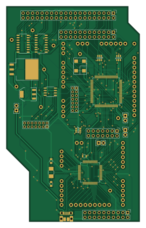
About the RL02InterfacePROTOTYPE PCB
RL02InterfacePROTOTYPE is an open source FPGA PCB design by ChrisPVille, published on GitHub under the GPL-3.0 license. It is a 2-layer board measuring 71.1 × 114.5 mm, with 147 components from 28 distinct parts.
Its main chip is the XC3S50A-4VQ100, from the FPGA family. Other key parts include the LMS1587ISX-3.3, AP2114HA-1.2, M25P10, AM26LV32CDR and TM4C1232D5PMI. By type, the board carries 83 connectors, 38 capacitors, 8 resistors, 7 ICs, 3 jumpers and 3 diodes.
From the project
RL02-USB Interface
This folder contains the KiCad (https://launchpad.net/kicad) project files, schematic symbols, and related footprints as well as generated schematics and gerber files.
I generally run the latest KiCad built from sources, so I may be using features that don't exist in the pre-built versions.
Main components on the RL02InterfacePROTOTYPE
RL02InterfacePROTOTYPE bill of materials (BOM)
147 components, 28 distinct parts — part numbers from the project's BOM.
| Qty | Part | Footprint | Refs |
|---|---|---|---|
| 1 | XC3S50A-4VQ100 | TQFP-100_14x14mm_Pitch0.5mm | U1 |
| 1 | LMS1587ISX-3.3 | TO-263 | U2 |
| 1 | AP2114HA-1.2 | SOT-223 | U3 |
| 1 | M25P10 | SOIC-8_3.9x4.9mm_Pitch1.27mm | U4 |
| 2 | AM26LV32CDR | SOIC-16_3.9x9.9mm_Pitch1.27mm | U5, U6 |
| 1 | TM4C1232D5PMI | TQFP-64_10x10mm_Pitch0.5mm | U7 |
| 1 | NX5032GA-16Mhz | C_1210_HandSoldering | X1 |
| 1 | CB3LV-3I-65M5360 | CTSCrystal | Y1 |
| 1 | USB-MICRO-B | MicroUSB-B | CON1 |
| 75 | TP | TP | P2, P4, P5, P6, P7, P8, P9, P10 +67 |
| 1 | SPI Debug | Pin_Header_Straight_2x07 | P20 |
| 1 | FPGA JTAG | 2x7_2.00mm_header | P21 |
| 1 | SPI Direct Program | 2x7_2.00mm_header | P22 |
| 1 | Data To Drive Disconnect | Pin_Header_Straight_2x12 | P48 |
| 1 | Drive Connector | Pin_Header_Straight_2x20 | P49 |
| 1 | ARM JTAG | Pin_Header_Straight_2x10 | P51 |
| 1 | CONN_01X02 | Pin_Header_Straight_1x02 | P64 |
| 3 | TP | TP | 1.2V, 3.3V, 5V |
| 1 | SPI_PROGRAM | Pin_Header_Straight_1x02 | JP1 |
| 2 | JUMPER | Pin_Header_Straight_1x02 | JP2, JP3 |
Show 8 more
| Qty | Part | Footprint | Refs |
|---|---|---|---|
| 3 | MMQA6V2T1GOSCT | SOT-23-6 | D1, D2, D3 |
| 21 | 1uF | C_0805 | C1, C3, C4, C5, C6, C7, C8, C9 +13 |
| 3 | 10uF | C_0805 | C2, C11, C17 |
| 11 | 0.1uF | C_0805 | C20, C21, C22, C23, C24, C31, C32, C33 +3 |
| 1 | 2.2uF | C_0805 | C28 |
| 2 | 10pF | C_0805 | C37, C38 |
| 6 | 100Ohm | R_0805 | R1, R2, R3, R4, R5, R6 |
| 2 | 10kOhm | R_0805 | R7, R8 |
RL02InterfacePROTOTYPE design files
The KiCad project lives in the ChrisPVille/RL02 repository on GitHub; these links point at the commit this page was built from.
RL02InterfacePROTOTYPE: common questions
What microcontroller does the RL02InterfacePROTOTYPE use?
The RL02InterfacePROTOTYPE is built around the XC3S50A-4VQ100, from the FPGA family.
How big is the RL02InterfacePROTOTYPE PCB?
The RL02InterfacePROTOTYPE measures 71.1 × 114.5 mm, has 2 copper layers and is 1.6 mm thick.
How many components are on the RL02InterfacePROTOTYPE?
147 components, from 28 distinct parts, with part numbers taken from the project's own BOM. The full bill of materials is listed on this page.
Where can I download the RL02InterfacePROTOTYPE design files?
From the ChrisPVille/RL02 repository on GitHub, which has the KiCad layout and the BOM; the links under Design files point to each one.
Can I use the RL02InterfacePROTOTYPE design in my own project?
Yes, under the terms of its GPL-3.0 license, which ChrisPVille chose for the repository.
Can I test firmware for the RL02InterfacePROTOTYPE without the hardware?
Yes. HardLabs builds a simulation of the board from its netlist and BOM, so you can run and debug FPGA firmware against it before you order a PCB.
More boards in RL02
Similar boards
 FPGA
Base board
GlasgowEmbedded
80 × 49 mm222 parts4L0BSD2.2k FPGA
Thunderscope Rev5.3
EEVengers
122.5 × 103.5 mm817 parts6LMIT1.3k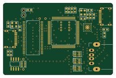 FPGA
Usb sniffer
ataradov
58.2 × 38.1 mm86 parts2LBSD-3-Clause1.3k FPGA
Tomu, I'm
theacodes
13 × 9.4 mm40 parts4LMIT1.1k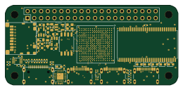 FPGA
Icepi zero
cheyao
65 × 30 mm143 parts4LSHL-2.1828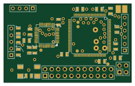 FPGA
Gcvideo
ikorb
49 × 30 mm44 parts4LNo license765