
C64-rf modulator replacement

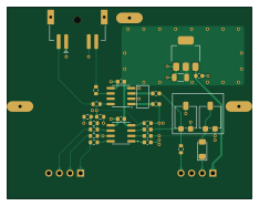
About the C64-rf modulator replacement PCB
C64-rf modulator replacement is an open source PCB design by christianeisendle, published on GitHub under the CERN-OHL-P-2.0 license. It is a 4-layer board measuring 58.4 × 45.7 mm, with 28 components from 13 distinct parts.
Other key parts include the LD1117S33TR and THS7314. By type, the board carries 10 resistors, 9 capacitors, 3 ICs, 3 connectors and 1 diode.
It belongs with the retro computing designs in this gallery.
From the project
Yet another C64 RF Modulator Replacement
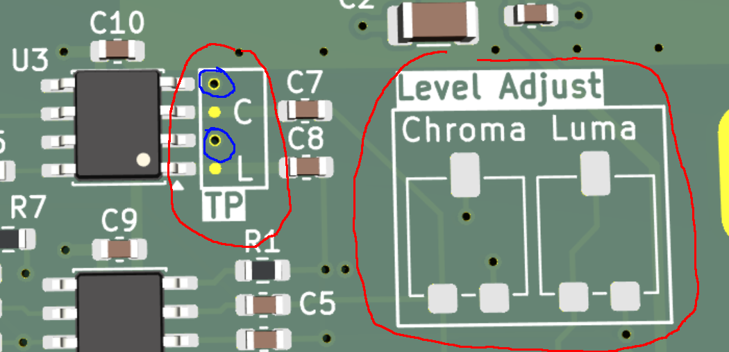
The testpoint labeled C exposes the Chroma signal and L the Luma signal. Next two these two testpoints there are vias (blue circled) with removed solder mask which can be used for low-inductive probing. Power up the C64 without a screen connected. Connect a scope to the testpoints and use the corresponding Luma and Chroma trimmer (right in the picture) to adjust the required signal levels: - Chroma: 0.3Vpp - Luma: 1Vpp
Main components on the C64-rf modulator replacement
C64-rf modulator replacement bill of materials (BOM)
28 components, 13 distinct parts.
| Qty | Part | Footprint | Refs |
|---|---|---|---|
| 1 | LD1117S33TR | SOT-223-3_TabPin2 | U1 |
| 2 | THS7314 | SOIC-8_3.9x4.9mm_P1.27mm | U2, U3 |
| 2 | C64_RFCon | PinHeader_1x04_P2.54mm_Vertical | J1, J2 |
| 1 | S-Video Out | MD2-40ST-SMT | J3 |
| 2 | 1k | Potentiometer_Vishay_TS53YL_Vertical | RV1, RV2 |
| 1 | 1N4148WT | D_MiniMELF | D1 |
| 3 | 1u | C_0603_1608Metric | C1, C9, C10 |
| 1 | 4u7 | C_1206_3216Metric | C2 |
| 5 | 100n | C_0603_1608Metric | C4, C5, C6, C7, C8 |
| 1 | 220 | R_0603_1608Metric | R1 |
| 1 | 1k | R_0603_1608Metric | R2 |
| 3 | tbd | R_0603_1608Metric | R3, R4, R7 |
| 5 | 75R | R_0603_1608Metric | R5, R6, R8, R9, R10 |
C64-rf modulator replacement design files
The KiCad project lives in the christianeisendle/c64-rf-modulator-replacement repository on GitHub; these links point at the commit this page was built from.
C64-rf modulator replacement: common questions
How big is the C64-rf modulator replacement PCB?
The C64-rf modulator replacement measures 58.4 × 45.7 mm, has 4 copper layers and is 1.64 mm thick.
How many components are on the C64-rf modulator replacement?
28 components, from 13 distinct parts. The full bill of materials is listed on this page.
Where can I download the C64-rf modulator replacement design files?
From the christianeisendle/c64-rf-modulator-replacement repository on GitHub, which has the KiCad layout and the schematic; the links under Design files point to each one.
Can I use the C64-rf modulator replacement design in my own project?
Yes, under the terms of its CERN-OHL-P-2.0 license, which christianeisendle chose for the repository.
Similar boards
Expansion Card Retrofit
FrameworkComputer
24 × 27.3 mm5 parts2LCC-BY-4.01.1k
Rgb to hdmi
hoglet67
77 × 97 mm67 parts2LGPL-3.01.0k
Buffer
53.9 × 23.2 mm13 parts2LGPL-3.01.0k
X1
121.9 × 81.3 mm51 parts2LGPL-3.01.0k
Amiga External
21.9 × 76.7 mm6 parts2LGPL-3.01.0k
Videoslotadapter
152 × 57.6 mm13 parts2LGPL-3.01.0k