
SpineTime Controller Board

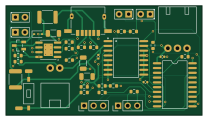
About the SpineTime Controller Board
SpineTime Controller Board is an open source AVR/Arduino PCB design by DaringCuteSeal, published on GitHub. It is a 2-layer board measuring 52 × 29 mm, with 40 components from 26 distinct parts.
Its main chip is the ATTINY1616, from the AVR/Arduino family. Other key parts include the DS3231 and TP4056. By type, the board carries 17 resistors, 6 capacitors, 5 diodes, 4 ICs, 4 connectors and 2 fuses.
It belongs with the power & battery and usb & debug tools designs in this gallery.
From the project
A neurodivergent-friendly linear clock gadget for time management in binder journals.
Spinetime is a ring binder-integrated linear clock [^1] designed to help students and neurodivergent individuals manage time and tasks more effectively. Users of Spinetime can visualize the passage of the day at a glance, providing aid especially for those who struggle with time blindness.
It is surprising to me that people have manufactured papers with time table template, but not invent something as simple as a pointer that tells you how far you have gone through your table. I suspect that this is because most people do not experience time blindness, and having some kind of pointer of the…
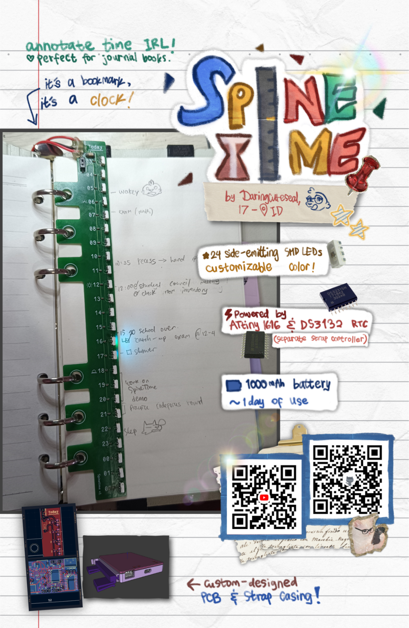
Main components on the SpineTime Controller Board
SpineTime Controller Board bill of materials (BOM)
40 components, 26 distinct parts — part numbers from the project's BOM.
| Qty | Part | Footprint | Refs |
|---|---|---|---|
| 1 | DS3231 ADI(亚德诺)/MAXIM(美信) | SOIC-16_L10.3-W7.5-P1.27-LS10.3-BL | U1 |
| 1 | TP4056 | SOIC-8-1EP_3.9x4.9mm_P1.27mm_EP2.41x3.3mm_ThermalVias | U2 |
| 1 | ATTINY1616 MICROCHIP(美国微芯) | SOIC-20_L12.8-W7.5-P1.27-LS10.3-BL | U3 |
| 1 | ~ DEALON(德艺隆) | USB-C-SMD_USB-TYPE-C-006 | U4 |
| 1 | DMP1045U HXY MOSFET(华轩阳电子) | SOT-23-3_L2.9-W1.5-P1.90-LS2.6-BR | Q1 |
| 1 | JST_BAT | JST_1x2_2.54mm-horizontal_1 | J1 |
| 1 | JST_BOOKMARK | JST_1x3_2.54mm-horizontal | J2 |
| 1 | CONN_UPDI | PinHeader_1x03_P2.54mm_Vertical | J3 |
| 1 | UART_DBG | PinHeader_1x03_P2.54mm_Vertical | J4 |
| 1 | 750m | Fuse_1812_4532Metric | F1 |
| 1 | 200m | Fuse_1812_4532Metric | F2 |
| 1 | SW_DIP_x01 | SW-SMD_CHS-01B | SW1 |
| 1 | LED_Y | LED_D2.0mm_W4.8mm_H2.5mm_FlatTop | D1 |
| 1 | LED_R | LED_D2.0mm_W4.8mm_H2.5mm_FlatTop | D2 |
| 1 | LED_R_LO | LED_D2.0mm_W4.8mm_H2.5mm_FlatTop | D3 |
| 1 | LED_R_IND. | LED_D2.0mm_W4.8mm_H2.5mm_FlatTop | D4 |
| 1 | 1SS404 | D_SOD-323 | D5 |
| 3 | 100u | C_1206_3216Metric | C1, C2, C5 |
| 3 | 0.1u | C_0402_1005Metric | C3, C4, C6 |
| 8 | 1K | R_0603_1608Metric | R1, R2, R3, R4, R9, R10, R16, R17 |
Show 6 more
| Qty | Part | Footprint | Refs |
|---|---|---|---|
| 3 | 10K | R_0603_1608Metric | R5, R6, R12 |
| 1 | 1M | R_0603_1608Metric | R7 |
| 1 | 255K | R_0603_1608Metric | R8 |
| 1 | 100K | R_0603_1608Metric | R11 |
| 1 | 330 | R_0603_1608Metric | R13 |
| 2 | 5K1 | R_0603_1608Metric | R14, R15 |
SpineTime Controller Board design files
The KiCad project lives in the DaringCuteSeal/spinetime repository on GitHub; these links point at the commit this page was built from.
SpineTime Controller Board: common questions
What microcontroller does the SpineTime Controller Board use?
The SpineTime Controller Board is built around the ATTINY1616, from the AVR/Arduino family.
How big is the SpineTime Controller Board?
The SpineTime Controller Board measures 52 × 29 mm, has 2 copper layers and is 0.8 mm thick.
How many components are on the SpineTime Controller Board?
40 components, from 26 distinct parts, with part numbers taken from the project's own BOM. The full bill of materials is listed on this page.
Where can I download the SpineTime Controller Board design files?
From the DaringCuteSeal/spinetime repository on GitHub, which has the KiCad layout, the schematic and the BOM; the links under Design files point to each one.
Can I use the SpineTime Controller Board design in my own project?
The repository has no license, so all rights stay with DaringCuteSeal. Use it as a reference, and ask the author before reusing the design.
Can I test firmware for the SpineTime Controller Board without the hardware?
Yes. HardLabs builds a simulation of the board from its netlist and BOM, so you can run and debug AVR/Arduino firmware against it before you order a PCB.
More boards in spinetime
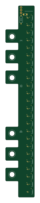
Similar boards
 AVR/Arduino
V4
stuartpittaway
30 × 50 mm38 parts2LCC-BY-NC-4.01.1k AVR/Arduino
ModuleV450
30 × 61.4 mm39 parts2LCC-BY-NC-4.01.1k AVR/Arduino
Easyduino Atmega Nano
Hanqaqa
43.4 × 18 mm30 parts4LCERN-OHL-P-2.0746 AVR/Arduino
Easyduino Atmega
68.8 × 53.6 mm35 parts4LCERN-OHL-P-2.0746 AVR/Arduino
UsbGpib
xyphro
54 × 15 mm21 parts2LMIT683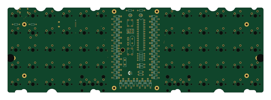 AVR/Arduino
Lumberjack
peej
284.7 × 94.2 mm149 parts2LMIT402